July 7, 2026 · simatic-axsiemensplc-programmingrequirementsio-listindustrial-automationcontrol-systems
I started this SIMATIC AX series by looking at core concepts, project structure, libraries, and toolchain behavior. That gave me a base for understanding the platform.
At some point, though, a toolchain series has to touch a machine, even if the machine is a small demo. Otherwise it starts to feel like polishing a wrench and never opening the cabinet.
So now I am moving the series into a practical demo project.
The project is a small tank-control system built as an engineering workflow. It is small enough to finish, but realistic enough to expose the decisions that make PLC projects messy in real life: signals, modes, the safety system, HMI commands, simulation signals, and the quiet little naming choices that later save time or create trouble.
It starts with a process diagram, a requirements review, and an I/O baseline. From there, the work can grow into SIMATIC AX code, WinCC Unified Elements screens, PLC-Lab simulation, and later electrical documentation.
This article captures the first engineering baseline for the demo.
I also recorded this step as a YouTube walkthrough if you prefer to see a little bit of the live process:
The Demo Process
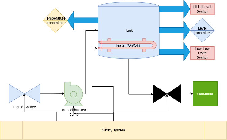
The demo process is a single tank system with filling, outlet flow, level measurement, temperature measurement, heating, level protection, and a hardwired E-stop / safety relay system.
It is a simple process on purpose. Simple here does not mean careless. It means the first project slice is small enough that every signal can be discussed instead of hidden inside a giant example.

The process diagram includes:
- a controlled liquid source valve;
- a VFD-controlled pump;
- a tank;
- an analog level transmitter;
- an analog temperature transmitter;
- high-high and low-low level switches;
- an on/off heater;
- an outlet valve to a consumer or downstream demand;
- a hardwired E-stop / safety relay system.
The diagram gives the first machine slice. It shows the equipment and signals that the control project has to represent before I start creating files in SIMATIC AX.
Hardwired Safety System
The emergency stop and safety chain are part of the first baseline.
Safety is one of those places where a demo can accidentally teach the wrong habit, so I am keeping the boundary very clear.
For this demo, safety is treated as a hardwired E-stop system with a safety relay. The standard PLC can monitor a safety-chain status, such as i_xSafetyChainOk, and use that status as a permissive for the control program and HMI.
That monitor input is not the certified safety function. The real safety function remains in the hardwired safety system.
When i_xSafetyChainOk is false, the standard PLC commands the demo outputs to safe states and shows the condition to the operator. Actuator energy removal belongs to the hardwired safety circuit.
Requirements Review
I used the process diagram as the input for a structured requirements and I/O review.
This is the part of the project where it is tempting to jump ahead and create the first project folder. I understand the temptation. A new project folder feels like progress. A requirements table feels like homework. But if the table is wrong, the project folder just becomes a very organized place to put confusion.
The review organized the project into:
- process narrative;
- equipment and flow path;
- actuators;
- sensors;
- hardwired safety system;
- operating modes;
- physical I/O;
- HMI and operator signals;
- simulation signals.
This is a useful place for AI assistance.
In this project I work with an AI engineering assistant I call Alex. Yes, Alex is AI. I call him Alex because it is much easier than saying “LLM instance 2036” every time I want help organizing a signal list. And… I just like to talk to “him”, not to “it”. :)
Alex can turn the diagram into tables, signal lists, and assumptions quickly. That is useful. He can also be confidently wrong, which is a very familiar engineering-team problem, just with faster typing.
The workflow only makes sense because I still review and approve the engineering decisions myself.
The result is a baseline I can use in the next article when I create the SIMATIC AX project, connect it to a public GitHub repository, and start the hardware configuration.
Operating Baseline
The first baseline uses five operating modes:
| Mode | Purpose |
|---|---|
| Stopped / disabled | Safe idle state before running |
| Manual | Commissioning and device testing |
| Automatic | Normal demo operation |
| Simulation / test | Engineering-only process simulation and fault forcing |
| Fault / protective hold | Held state after a blocking process or device fault |
Manual mode obeys safety and process-protection interlocks. A manual pump, heater, or valve request still has to pass the same basic protection rules as automatic operation.
That is important because manual mode is often where demos become unrealistic. In a real machine, “manual” should help with commissioning and testing. It should not become a magic bypass button.
Safety-chain status is a hardwired safety-system permissive. It blocks normal actuator commands while the hardwired safety system handles the actual safety function.
Physical I/O Baseline
The first physical I/O list is now clear enough for the SIMATIC AX hardware configuration.
This is the point where the diagram starts to turn into addresses, modules, and code interfaces. It still looks like a list, but it is already shaping the project structure.
Analog Inputs
| Signal | Meaning | First baseline |
|---|---|---|
i_iTankLevelRaw | Tank level raw input | 4-20 mA, Siemens raw 0..27648 |
i_iTankTemperatureRaw | Tank temperature raw input | 4-20 mA, Siemens raw 0..27648 |
For the first demo, tank level uses a fixed scaling:
- raw
0maps to0%; - raw
20000maps to100%.
Temperature uses the demo range:
- raw
0..27648maps to0..100 deg C.
Level is displayed and controlled in percent. Temperature is displayed and controlled in degrees Celsius.
Digital Inputs
| Signal | Meaning |
|---|---|
i_xLevelHighHighOk | High-high level OK input |
i_xLevelLowLowOk | Low-low level OK input |
i_xSafetyChainOk | Safety-chain healthy monitor |
i_xPumpRunningFb | Pump/VFD running feedback |
i_xPumpVfdFault | VFD fault feedback |
The high-high and low-low inputs use fail-safe OK semantics:
TRUEmeans the condition is healthy;FALSEmeans the protective condition exists.
So i_xLevelHighHighOk = FALSE means high-high level exists, and i_xLevelLowLowOk = FALSE means low-low level exists.
This naming keeps the physical contact philosophy clear in the PLC code and HMI.
It is a small naming decision, but those small decisions are exactly where control projects either become readable or become archaeology for the next person.
Outputs
| Signal | Meaning |
|---|---|
q_xLiquidSourceValveOpenCmd | Open command for the source valve |
q_xPumpVfdEnable | VFD Enable command |
q_xPumpVfdRun | VFD Run command |
q_iPumpSpeedCommandRaw | VFD speed reference as 0-10 V, raw 0..27648 |
q_xHeaterEnable | On/off heater command |
q_xOutletValveOpenCmd | Outlet valve open command |
The VFD interface for the first baseline uses digital Enable, digital Run, and an analog 0-10 V speed reference. Pump speed demand is calculated in percent and mapped to the raw analog output.
The heater is on/off. Low-low level switches the heater off.
The outlet valve is on/off. It closes on low-low level, stopped state, fault state, or safety not OK. High-high level inhibits filling.
HMI Scope
The first HMI scope is intentionally small and practical.
The operator needs:
- mode selection;
- start, enable, and stop commands;
- reset;
- level setpoint;
- temperature setpoint;
- manual pump, heater, and valve requests;
- status displays;
- alarm and warning status.
The first demo uses reset-only recovery. Alarm and warning statuses are displayed and auto-acknowledged. The operator uses reset to clear held conditions after the sources are healthy.
I am keeping the first HMI scope boring on purpose. Boring is good when the first version needs to run and prove the workflow.
Simulation controls belong on an engineering screen, not on the normal operator surface.
Simulation Signals
PLC-Lab is the selected simulation direction for the project arc.
Simulation is not the work of this article, but the baseline already needs to leave room for it. If I wait until the simulation article to think about simulated signals, I will probably rename half the project later. I prefer to avoid that little future gift to myself.
For the internal baseline, the simulated level protection thresholds are:
- low-low at
10%; - high-high at
90%.
Because the high-high and low-low signals are OK signals:
sim_xLevelLowLowOkbecomesFALSEwhen simulated level is<= 10%;sim_xLevelHighHighOkbecomesFALSEwhen simulated level is>= 90%.
The simulation layer also needs tank level, tank temperature, consumer demand, safety-chain status, pump running feedback, and fault-forcing signals for engineering tests.
Approved First Baseline
The Article 19 review produced this first baseline:
- project name:
AXtankDemoProject; - controller family: S7-1200 G2;
- process diagram approved as the first machine slice;
- level transmitter:
4-20 mA; - temperature transmitter:
4-20 mA; - VFD speed reference:
0-10 V; - Siemens analog raw range:
0..27648; - fail-safe OK semantics for high-high and low-low level inputs;
- hardwired E-stop / safety relay system, with PLC monitoring only;
- protected manual mode;
- reset-only HMI recovery;
- engineering-only simulation controls;
- PLC-Lab selected as the simulation direction;
- only two cups of coffee today doesn’t feel enough… oh, this is from another story.
This is enough information to create the first project structure in SIMATIC AX.
It may not look as exciting as a screen full of code, but this is the part that makes the code possible without guessing.
What Comes Next
In the next article, I will create the public GitHub repository for AXtankDemoProject, create the SIMATIC AX project, select the S7-1200 G2 hardware modules, and build the first hardware configuration from this I/O baseline.
That is enough work for one article.
I have learned that “just one more small step” is how a practical article quietly becomes too large to be useful. So Article 20 will stay focused: a shareable repository with the first project files, a documented controller and module selection, and a compiled hardware configuration for the tank demo.
Discussion on LinkedIn: SIMATIC AX Tank Control Demo: Requirements and I/O Baseline.
Working on something similar?
I am Yuriy Mosiyenko — I design and program industrial control systems, mostly Siemens, as a one-person practice based in Bedford, Nova Scotia, working with customers across Canada. If you have a controls project you cannot staff internally, tell me what you are building.
