
July 31, 2026 · SIMATIC AXSiemensPLC programmingindustrial automationcontrol systems
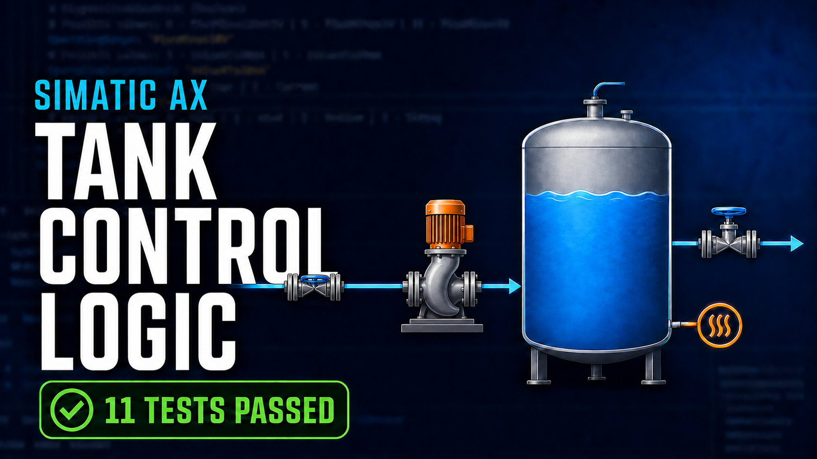
In TIA Portal, creating the FBs and DB structure is only the beginning. The real engineering starts when I decide what each block is allowed to do, which protection has priority, and how one scan passes those decisions from inputs to outputs.
Article 21 brought my SIMATIC AX tank demo to that point. I had one shared interface, two mapping functions, six control blocks, and a readable main-program order. Everything compiled, but the block bodies were intentionally empty. Article 22 gives that structure behavior and proves the decisions that matter.
My goal was not to walk through every changed line. I wanted a controls engineer to open the project and answer practical questions quickly: Where does a raw analog value become percent? Can Manual bypass protection? What happens on low-low level? Why can the pump not start as soon as the source valve opens? Which part of the project proves those answers?
This remains an R&D demo. I have not commissioned this logic on a customer machine or real tank hardware. I am using my TIA Portal experience as the bridge while I study how the same engineering discipline fits SIMATIC AX.
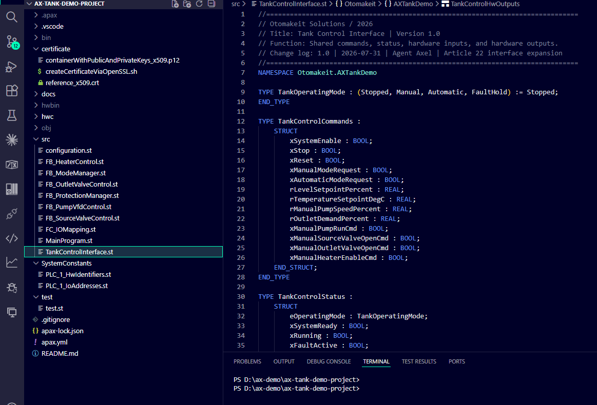
The completed source structure keeps the shared interface, mappings, protection, mode, and equipment blocks visible in one project view.
Watch the programming walkthrough
I also recorded a YouTube walkthrough of this programming session if you prefer to see the SIMATIC AX workflow and the test run directly:
Watch the Article 22 video on YouTube
Add the timer where dependencies belong
The filling sequence needs a three-second delay between opening the source valve and permitting the pump. Rather than inventing a timer, I added Siemens’ @ax/system-timer package in apax.yml:
dependencies:
  "@ax/hw-s7-1200g2": ^4.6.0
  "@ax/system-timer": "10.4.66"
apax.yml is the human-maintained project manifest. It says which package the source code needs. AX maintains apax-lock.json as the exact installed-package record. I commit that lock file, but I do not edit it by hand.
Match the module configuration to the real signal type
The tank demo uses an SM 1233 AI4/AQ4. Level and temperature are 4–20 mA transmitter signals. The VFD reference is voltage.
For each used analog input, the relevant settings are:
OperatingRangeOutput: 'Value4To20mA'
OperatingType: 'Current'
AQ0 remains configured as Voltage. The physical channel supports ±10 V, but this application uses 0 to +10 V for the pump-speed reference.
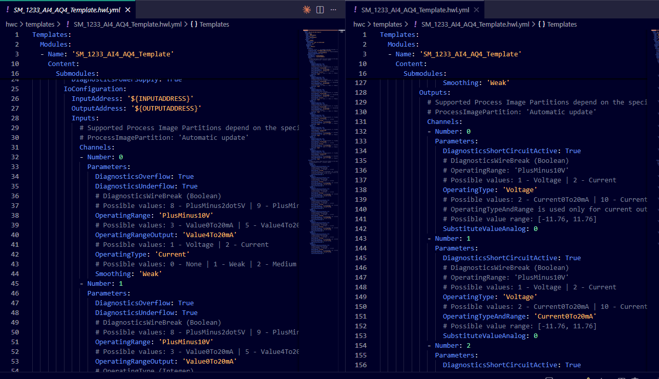
The used analog inputs are configured for 4–20 mA current signals, while AQ0 remains a voltage output for the VFD speed reference.
Convert addresses and counts at the mapping boundary
I declare physical addresses once in configuration.st:
i_xSourceWaterAvailable AT %I0.5 : BOOL;
i_iTankLevelRaw AT %IW64 : INT;
i_iTankTemperatureRaw AT %IW66 : INT;
q_iPumpSpeedRaw AT %QW64 : INT;
AI0 %IW64 is tank level. AI1 %IW66 is tank temperature. AQ0 %QW64 is the pump-speed reference. On real equipment, a flow switch connected to DI5 %I0.5 confirms that water is present before the pump is allowed to run.
After clamping, the level conversion is:
FC_ScaleRawToPercent := rRawClamped * REAL#100.0 / REAL#27648.0;
Raw 13824 therefore becomes 50%. The control blocks work with engineering values rather than unexplained register counts.
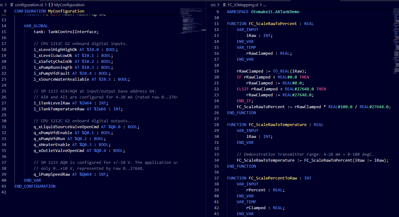
Physical addresses are declared once, then mapping converts raw 0–27,648 values into percent and degrees Celsius.
Manual and Automatic select demand, not permission
The operator selects Manual or Automatic. Missing or conflicting selection leaves the system stopped and raises a warning. Automatic filling uses a simple retained request around the level setpoint:
ELSIF tank.status.rTankLevelPercent <= (rLevelSetpoint - LEVEL_BAND_HALF_WIDTH_PERCENT) THEN
    _xAutomaticFillRequest := TRUE;
ELSIF tank.status.rTankLevelPercent >= (rLevelSetpoint + LEVEL_BAND_HALF_WIDTH_PERCENT) THEN
    _xAutomaticFillRequest := FALSE;
END_IF;
LEVEL_BAND_HALF_WIDTH_PERCENT is REAL#5.0. With a 50% setpoint, filling begins at or below 45% and stops at or above 55%. Inside the band, the previous fill request is retained. This prevents rapid cycling without introducing PID.
Manual mode lets the operator request equipment. It does not become a maintenance bypass hidden behind a mode bit. Manual and Automatic answer, “What does the operator want?” The equipment blocks separately answer, “What may the equipment do right now?”
A pump request can be true while pump permission is false because the valve is still closed, the priming timer is incomplete, the flow switch connected to DI5 has not confirmed water is present, or a stop condition is active. The mode changes the source of demand, not the meaning of a permissive.
Low-low recovery needs a selective path
The protection manager latches safety-chain, VFD, high-high, low-low, and dry-run faults. Reset is edge-based, and each latch clears only when its own initiating condition is safe and a new reset edge arrives.
Low-low level needs a narrow recovery path. A full shutdown would correctly stop the outlet and heater, but it would also stop the inlet pump and make recovery impossible. The mode manager therefore permits filling only when low-low is the only fault and the low-low input remains active.
The outlet closes and the heater is inhibited. The source valve and pump may use their normal protected sequence to restore level. When low-low becomes healthy, recovery filling stops. The controller remains in FaultHold until the operator supplies a fresh reset edge.
High-high level, VFD fault, and an unhealthy safety chain remain full-stop faults. If another full-stop fault is present with low-low, the refill request is not created.
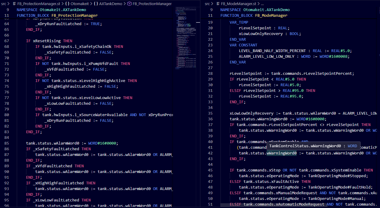
Protection remains latched, while the mode manager permits only the narrow low-low refill path needed to recover level.
Open the valve, wait, prove water, then run the pump
The source valve block runs before the pump block. The pump block uses Siemens’ timer:
_tonPrimingDelay(
    signal := tank.hwOutputs.q_xLiquidSourceValveOpenCmd AND tank.status.xFillDemand,
    duration := PRIMING_DELAY
);
tank.status.xPumpPrimed := _tonPrimingDelay.output;
PRIMING_DELAY is exactly LT#3s. After that timer completes, pump permission still requires the source valve command, the primed state, and xSourceWaterAvailable.
The sequence is deliberate: the source valve opens first, the program waits three seconds, and a flow switch connected to DI5 confirms that water is present before the pump may run. A timer cannot prove that water arrived.
While running, the speed command is clamped to 10–100%. Automatic filling uses 60%, and selective low-low recovery uses 50%. When the pump is stopped, not yet primed, or not permitted, the analog command returns to 0%.
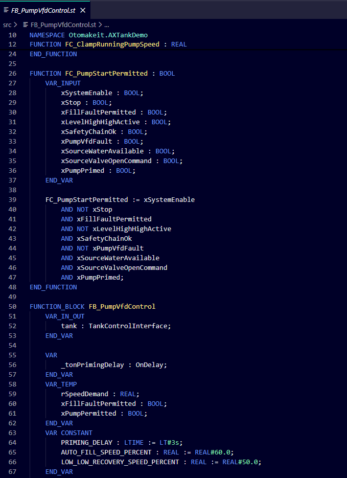
The pump permission combines the source-valve command, the three-second primed state, and water proof from the flow switch connected to DI5.
Keep the outlet and heater behavior honest
The operator’s outlet request remains a percentage from 0 to 100. The current physical output is digital, so any permitted non-zero Automatic demand opens the valve fully. In Manual, both the manual open command and a non-zero percentage are required.
The heater uses ±1 °C hysteresis around its setpoint. Manual heat remains protected. Low-low level, any latched fault, or an unhealthy safety chain inhibits the heater.
Let the main scan explain the application
The final call order is short enough to read as the control story:
_fbProtectionManager(tank :=tank);
_fbModeManager(tank :=tank);
_fbSourceValveControl(tank:=tank);
_fbPumpVfdControl(tank:=tank);
_fbOutletValveControl(tank:=tank);
_fbHeaterControl(tank:=tank);
Input mapping runs above these calls. Output mapping runs below them. Protection is evaluated before mode and equipment, and the source valve runs before the pump so the pump sees the current source-path command.
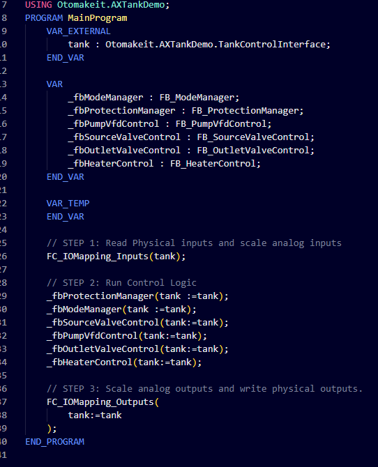
One scan reads inputs, evaluates protection, creates demand, controls equipment in process order, and writes outputs.
Build checks compilation; AxUnit checks behavior
The full suite has eleven tests. It checks dry-run latching and recovery, missing flow-switch proof at DI5, analog scaling and clamps, pump-speed limits, fresh-reset low-low behavior, the ±5% automatic band, selective low-low recovery, high-high shutdown, the digital outlet representation, and pump inhibition before the priming delay.
The final verification passed the hardware compile, compiled both S7 and LLVM software targets with zero errors, and passed all eleven AxUnit tests.
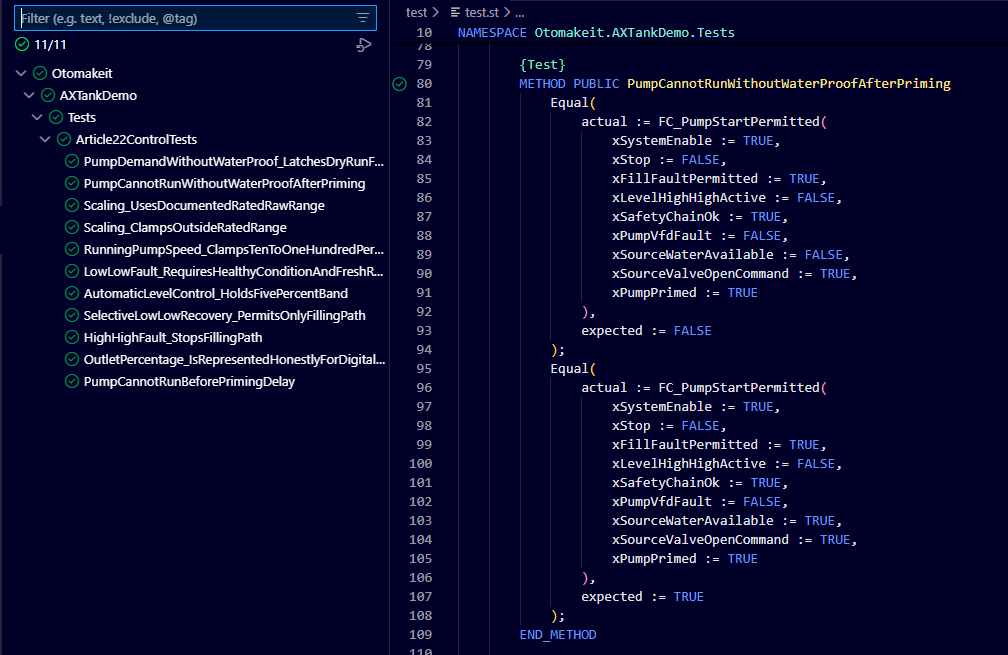
The complete Article 22 AxUnit suite passes 11 of 11 tests, including pump inhibition without water proof and before the priming delay.
Discussion on LinkedIn: Programming a Siemens PLC in SIMATIC AX.
Working on something similar?
I am Yuriy Mosiyenko — I design and program industrial control systems, mostly Siemens, as a one-person practice based in Bedford, Nova Scotia, working with customers across Canada. If you have a controls project you cannot staff internally, tell me what you are building.
