
July 21, 2026 · SIMATIC AXPLC programmingStructured Textindustrial automationSiemens
In Article 19, I turned the tank process into requirements and a first I/O baseline. In Article 20, I created the hardware project, generated the hardware constants, and reached a clean compile.
Article 21 gives that project a software structure.
I created one shared tank interface, two I/O mapping functions, six control function blocks, one global tank variable, and an explicit main-program call order. The functions and blocks are intentionally placeholders at this stage. Their job is to define responsibilities and prove that the interfaces compile before the real control behavior arrives.
A blank main program can make almost any first idea look tidy. Later, it can become a very organized place to hide confusion. Building the skeleton first gives every future piece of logic a clear home.
This is a public R&D demo. I have not deployed this SIMATIC AX structure on a customer project, and I am not presenting it as the only correct architecture. I am testing how engineering patterns I know from PLC work translate into AX.
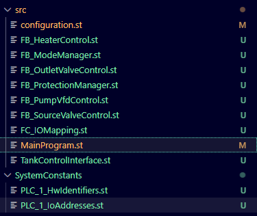
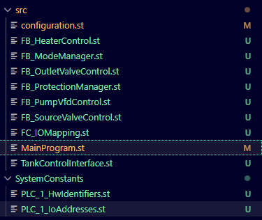
Figure 1: The Article 21 source tree separates mapping, control responsibilities, the main program, and the shared tank interface before control behavior is added.
Six Short Tutorials, One Engineering Story
I changed the video format for this article. Instead of recording one long walkthrough, I made six short tutorials. Each one answers one practical AX question: how to create an ST file, function, function block, UDT, global variable, or main-program call.
The article has a different job. It connects those individual operations into one software architecture and explains why the pieces are arranged this way.
Start With Responsibilities
Before creating files, I divided the tank application into functional responsibilities.
The input mapping function will read physical inputs and convert the two raw analog values into engineering values: tank level in percent and tank temperature in degrees Celsius.
The mode manager will own the stopped, manual, automatic, and fault-hold states.
The protection manager will evaluate the high-high and low-low level signals, the pump VFD fault, and the general safety-chain monitor.
The pump, source-valve, outlet-valve, and heater blocks will each own their equipment behavior.
Output mapping will take the software-side commands, scale the pump-speed demand from percent to the raw analog-output range, and write the physical outputs.
For this demo, analog scaling belongs inside the mapping functions. The control blocks work with percent and degrees Celsius. They do not need to know the raw count range of an analog module.
i_xSafetyChainOk stays inside a strict boundary. It is monitored by standard PLC logic as a status and permissive. The certified safety function remains outside this standard control program.
How to Create Structured Text Files in SIMATIC AX
One Shared Interface From Named Child UDTs
The central data contract is TankControlInterface. It is composed from four named child UDTs:
TYPE TankControlInterface :
    STRUCT
        commands : TankControlCommands;
        status : TankControlStatus;
        hwInputs : TankControlHwInputs;
        hwOutputs : TankControlHwOutputs;
    END_STRUCT;
END_TYPE
Each child has a clear role:
commandscarries requests, mode selections, manual commands, and setpoints into the control layer.statuscarries mode, ready/running/fault states, process values, protection indications, and alarm/warning words out of the control layer.hwInputskeeps raw physical feedback and analog input values together.hwOutputsholds software-side equipment commands before output mapping converts them to hardware values.
The split keeps raw hardware data separate from operator commands and engineering values. It also makes the future HMI boundary easier to see.
How to Create a UDT in SIMATIC AX
Compiler Lesson 1: Name The Child Structures
My first version placed anonymous nested STRUCT declarations directly inside TankControlInterface. The ST compiler rejected that form.
I corrected it by declaring TankControlCommands, TankControlStatus, TankControlHwInputs, and TankControlHwOutputs as named types, then composing the parent interface from them.
The result is a little more verbose and much easier to read. Sometimes a compiler correction is an architecture review with a shorter meeting.
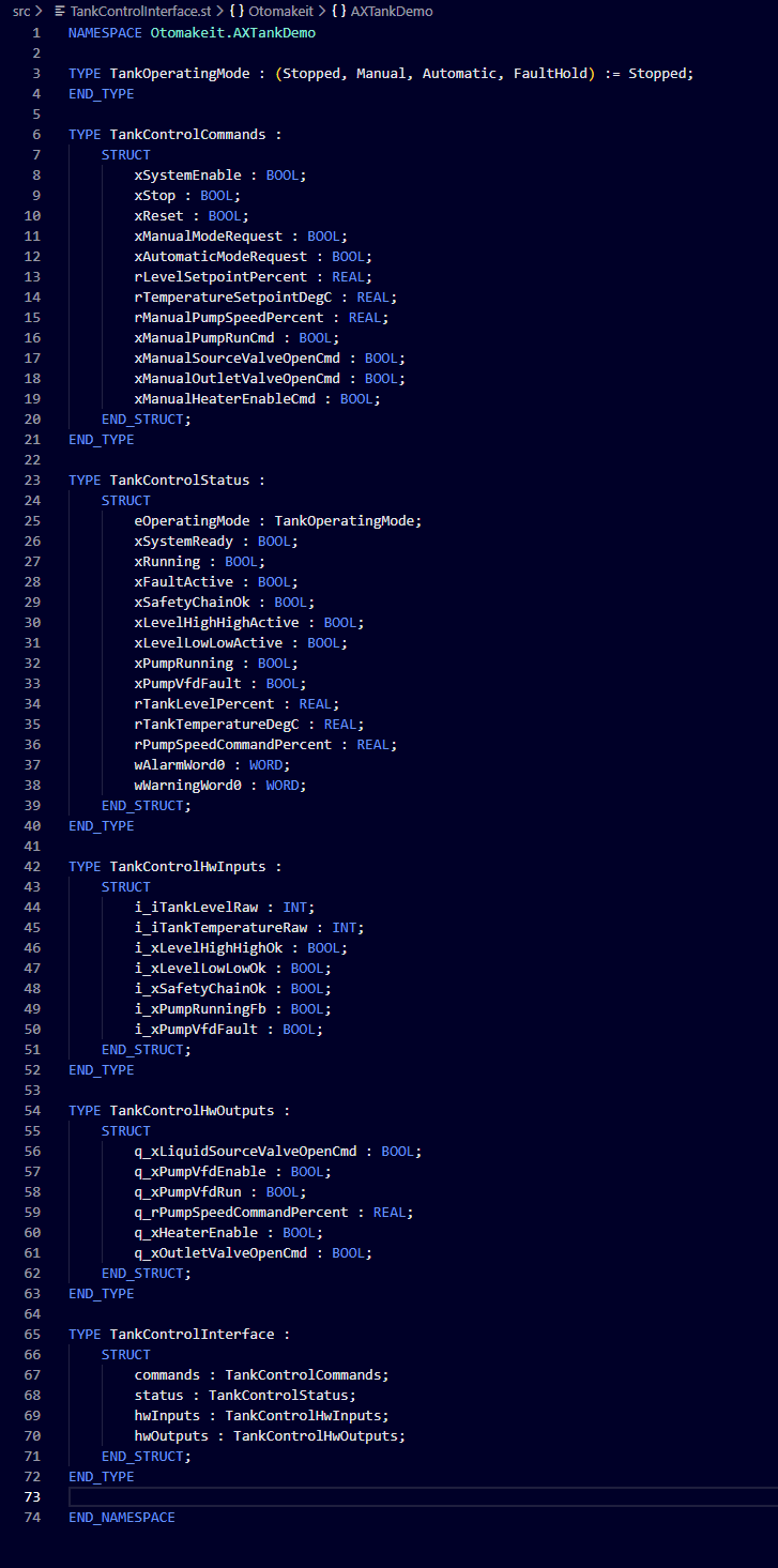
Figure 2: TankControlInterface composes commands, status, raw hardware inputs, and software-side outputs from four named child UDTs.
Mapping Defines The Hardware Boundary
Both mapping functions live in FC_IOMapping.st and receive the shared interface through VAR_IN_OUT.
FUNCTION FC_IOMapping_Inputs
    VAR_IN_OUT
        tank : TankControlInterface;
    END_VAR

    // Article 21 placeholder.
    // Later: read physical inputs and scale raw analog values.
    ;
END_FUNCTION
FC_IOMapping_Outputs follows the same pattern. It will later scale the pump-speed command from percent to raw output counts and write the physical outputs.
The semicolon has the easiest job in Article 21. That is fine. The mapping functions already establish a real interface and a clear hardware boundary while the implementation is still waiting for Article 22.
How to Create a Function in SIMATIC AX
Blank Function Blocks Still Need Instance State
The control layer contains six function block types:
FB_ModeManagerFB_ProtectionManagerFB_PumpVfdControlFB_SourceValveControlFB_OutletValveControlFB_HeaterControl
Every FB receives the same tank : TankControlInterface through VAR_IN_OUT. Each block will later own behavior and internal state for one responsibility.
Compiler Lesson 2: VAR_IN_OUT Is Not Instance State
My first blank FB contained only the VAR_IN_OUT parameter. The compiler still rejected it as a blank function block because an FB needs instance state and VAR_IN_OUT does not count.
I added a temporary private variable:
FUNCTION_BLOCK FB_ModeManager
    VAR_IN_OUT
        tank : TankControlInterface;
    END_VAR

    VAR
        _xPlaceholderState : BOOL;
    END_VAR

    // Article 21 placeholder.
    ;
END_FUNCTION_BLOCK
_xPlaceholderState has no control purpose. Article 22 can replace it with real state as the mode, protection, pump, valve, and heater logic is implemented.
How to Create a Function Block in SIMATIC AX
One Global Tank Connects The Program
The shared interface becomes one global variable in configuration.st:
USING Otomakeit.AXTankDemo;

CONFIGURATION MyConfiguration
    TASK Main(Priority := 1);
    PROGRAM P1 WITH Main: MainProgram;

    VAR_GLOBAL
        tank : TankControlInterface;
    END_VAR
END_CONFIGURATION
MainProgram references the same object through VAR_EXTERNAL and declares one instance of each FB.
Functions and function blocks are different at the call boundary. The two mapping functions are called directly. Each FB type must first be instantiated in MainProgram, then its instance is called.
One global tank keeps this first demo easy to inspect. A larger application may need narrower interfaces or separate equipment-unit data, but this skeleton only grows when the application gives it a reason.
How to Create a Global Variable in SIMATIC AX
Make The Scan Order Visible
The main program reads like the architecture diagram:
// STEP 1: Read physical inputs and scale analog inputs.
FC_IOMapping_Inputs(tank);

// STEP 2: Run control structure.
_fbModeManager(tank := tank);
_fbProtectionManager(tank := tank);
_fbPumpVfdControl(tank := tank);
_fbSourceValveControl(tank := tank);
_fbOutletValveControl(tank := tank);
_fbHeaterControl(tank := tank);

// STEP 3: Scale analog outputs and write physical outputs.
FC_IOMapping_Outputs(tank := tank);
Input mapping runs first so every control block sees the current physical state and engineering values. Mode and protection run before the equipment blocks so the later pump, valve, and heater logic can use current operating states and permissives. Output mapping runs last and writes the commands created during the same scan.
The calls do not create useful machine behavior yet. They establish deterministic execution order and prove that the function types, FB instances, shared interface, and global data connect correctly.
SIMATIC AX Main Program: Call Functions and Function Blocks
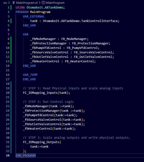
Figure 3: MainProgram shares one external tank interface, instantiates six control blocks, and runs input mapping, control, then output mapping.
Several Declarations Can Share One ST File
SIMATIC AX allows several declarations in one ST file. Article 21 uses that in two places:
- All four child UDTs and the parent
TankControlInterfaceshareTankControlInterface.st. - Both mapping functions share
FC_IOMapping.st.
I placed the six function blocks in focused files because they own separate responsibilities. That makes navigation, review, Git history, and the next implementation step easier. It is an engineering workflow choice, not a compiler requirement.
The same boundary applies to USING. A file already declared inside NAMESPACE Otomakeit.AXTankDemo can see declarations in that namespace without USING Otomakeit.AXTankDemo;. The current public commit still contains that redundant line in the mapping and FB files, and it compiles.
configuration.st and MainProgram.st sit at the global boundary. USING Otomakeit.AXTankDemo; is useful there for unqualified type and block names. A fully qualified type name is another valid option.
Compile The Structure Before Adding Behavior
After connecting the types, global data, instances, and calls, I ran apax build. The verified build passed the S7 and LLVM targets with zero errors.
The screenshot below has a narrower claim. It visibly shows the final LLVM Structured Text compiler stage finishing with zero errors.
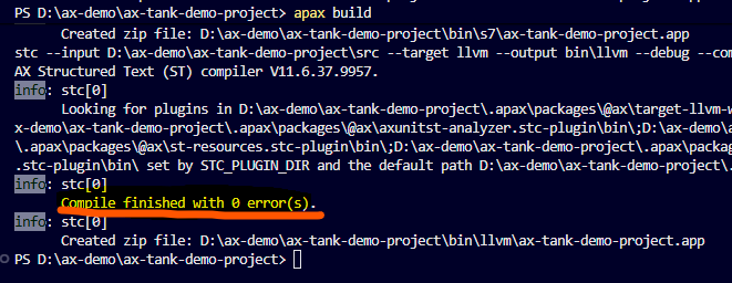
Figure 4: The final LLVM Structured Text compiler stage completes with zero errors.
The source is recorded in public commit 6403d31 with the message Add Article 21 tank control software skeleton.
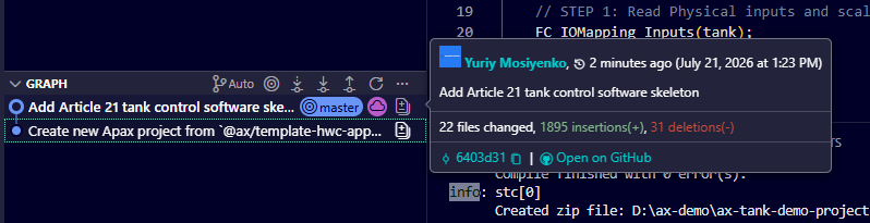
Figure 5: Commit 6403d31 records the Article 21 tank-control software skeleton on master.
What Comes Next
The project now has a stable place for every major control responsibility. Article 22 can add mode handling, protection evaluation, pump and valve control, heater behavior, analog mapping, alarms, and simulation support one piece at a time.
The useful result from Article 21 is a compiling contract and a visible execution order. When the behavior arrives, the project already knows where it belongs.
If you have used SIMATIC AX on a real project and prefer a different interface pattern, I would like to hear how you structured it. This is exactly why I publish the R&D work while I am still studying it.
Working on something similar?
I am Yuriy Mosiyenko — I design and program industrial control systems, mostly Siemens, as a one-person practice based in Bedford, Nova Scotia, working with customers across Canada. If you have a controls project you cannot staff internally, tell me what you are building.
