May 6, 2026 · siemenssimatic-axwincc-unified-elementsopc-uaplcsim-advancedhmiindustrial-automationplc-programming
Why This Article Exists
In the previous article I introduced WinCC Unified Elements — what it is, how it differs from TIA Portal HMI, and why the code-based approach changes what is possible. That article was conceptual.
This one is hands-on.
I took the TempController function block from the unit testing articles — the one I built in Articles 9 and 10 — and connected it to a WinCC Unified Elements screen running in a browser. Four OPC UA tags. One screen. The whole thing built from a terminal without touching the TIA Portal GUI.
Here is what that loop looks like in practice.
The Setup — Two Projects Sitting Side by Side
Article 11 described the workspace structure: the PLC project and HMI project are separate apax projects, connected at runtime over OPC UA. In my demo folder, that looks like this:
AX CLI/
├── ax-getting-started/   ← AX PLC project (TempController FB, AxUnit tests)
└── ue-intro/             ← WinCC UE HMI project (the screen we build today)
The PLC side already existed from the unit testing articles. The HMI side was created with a single apax create @ue/empty-device command followed by apax dm setup-device.
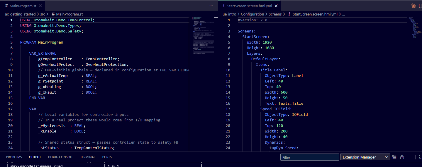
They are two separate projects, but AX Code shows them in the same Explorer panel. One git at the parent folder tracks both. One commit can change an OPC UA pragma in the PLC code and the corresponding tag definition in the HMI — that is the “unified” part of the stack.
Step 1 — Exposing Variables via OPC UA Pragmas
The TempController FB has inputs and outputs — i_rActualTemp, i_rSetpoint, q_xHeating, q_xFault. But those are FB-local. The HMI cannot reach inside a function block instance; it needs global variables that the OPC UA server can publish.
The solution is a second VAR_GLOBAL block in configuration.st with two pragmas:
{S7.extern = ReadWrite}
{OpcUa.AccessLevel = ReadWrite}
VAR_GLOBAL
    g_rActualTemp  : REAL;    // HMI reads actual temperature
    g_rSetpoint    : REAL;    // HMI operator writes desired setpoint
    g_xHeating     : BOOL;    // HMI reads heater state
    g_xFault       : BOOL;    // HMI reads fault state
END_VAR
One pragma makes the variables accessible to external clients (S7.extern). The other tells the OPC UA compiler to generate nodes for them (OpcUa.AccessLevel).
I also added {OpcUa.NodeGenerator.IdType = SymbolName} at the CONFIGURATION level. This makes the OPC UA node addresses use the variable name — s=g_rSetpoint — rather than a numeric ID that changes whenever you reorder declarations. For a demo, that matters. Stable, readable addresses are much easier to debug when you are browsing the server namespace for the first time.
Then in MainProgram.st, I wired the globals into the existing FB call:
// HMI operator writes g_rSetpoint; controller reads it
gTempController(
    i_rActualTemp := g_rActualTemp,
    i_rSetpoint   := g_rSetpoint,
    i_rHysteresis := _rHysteresis,
    i_xEnable     := _xEnable
);

// After the FB call, mirror outputs back to globals for HMI to read
g_xHeating := gTempController.q_xHeating;
g_xFault   := gTempController.q_xFault;
g_rActualTemp serves a dual role in this demo: the HMI displays it, and it also feeds the controller. In a real project, the actual temperature would come from I/O mapping. For the demo, PLCSIM Advanced lets me write g_rActualTemp directly from an OPC UA client to simulate sensor input.
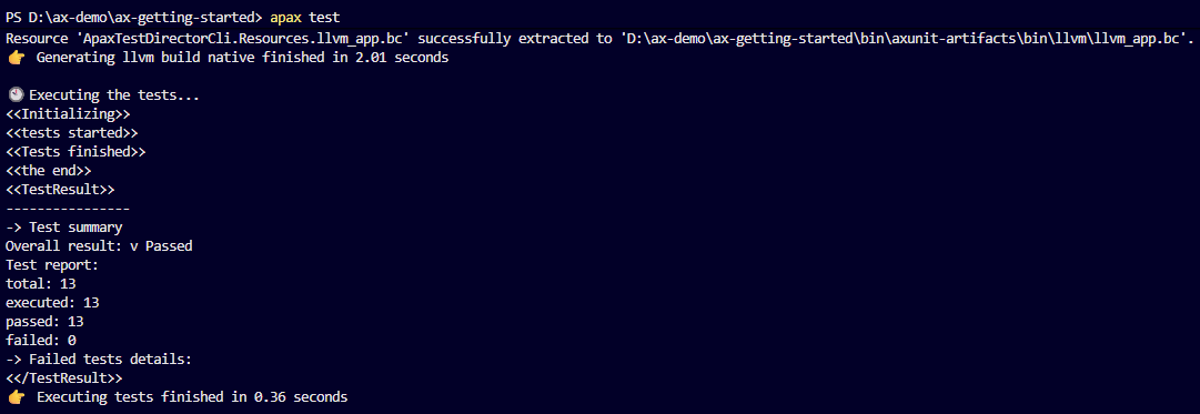
After these changes, apax build compiled both targets clean — and 13 of 13 AxUnit tests still passed. The pragma changes did not touch the control logic.
Step 2 — Connecting HMI Tags to OPC UA
On the HMI side, I created Configuration/Tags/TempControllerTags.hmi.yml. The connection definition looks like this:
#Version: 2.0

OpcuaConnections:
  PLC_TempController:
    AuthenticationMode: 2
    AuthenticationUserId: User1
    AuthenticationPassword: <demo-password>
    ConnectionType: OpcUaConnection
    DisabledAtStartup: False
    InitialAddress: opc.tcp://192.168.0.1:4840
    ManagerNumber: 3
    MessageMode: 1
    Policy: 1
A few things worth noting here. AuthenticationMode: 2 means username/password authentication. The AX hardware configuration created the PLC user, and WinCC UE uses that user to connect to the PLC OPC UA server. Policy: 1 and MessageMode: 1 are both None — no encryption or signing. For PLCSIM Advanced running locally this is acceptable for a demo. For a real deployment you would set these to match your PLC’s OPC UA server security policy and handle secrets outside a public repository.
ManagerNumber: 3 is the internal manager number for the OPC UA communication driver. It is defined in the system’s ManagerNumbers.sym.yml — you do not pick this number yourself; it is assigned when the OpcUaCommunication domain function is activated.
The four tags:
SimpleTags:
  TC_ActualTemp:
    DataType: Real
    Connection: PLC_TempController
    AcquisitionMode: CyclicOnUse
    AcquisitionCycle: T1s
    ControllerDataType: OpcUa_Float
    Address: V:1$DA$ns=4;s=g_rActualTemp
    ManagerNumber: 3

  TC_Setpoint:
    DataType: Real
    Connection: PLC_TempController
    AcquisitionMode: CyclicOnUse
    AcquisitionCycle: T1s
    ControllerDataType: OpcUa_Float
    Address: V:1$DA$ns=4;s=g_rSetpoint
    ManagerNumber: 3
The AcquisitionCycle: T1s references a predefined system cycle — the device template includes T1s, T500ms, T100ms, and others in the system artifacts. You reference them by name without having to define them yourself.
ControllerDataType: OpcUa_Float maps to the OPC UA Float node type, which corresponds to the AX REAL type (32-bit IEEE 754). For the Boolean tags, OpcUa_Boolean maps to AX BOOL.
The Address value is not the slash-style browse path you might expect from an OPC UA browser. WinCC UE stores data-access tag addresses in its own format: V:1$DA$ followed by the OPC UA NodeId. In this case the AX OPC UA nodes are stable symbolic NodeIds, so g_rActualTemp becomes V:1$DA$ns=4;s=g_rActualTemp on my running PLCSIM Advanced instance. The numeric namespace index can be remapped by the live server; the namespace URI behind this one is http://Server Interface_1.
I also needed to activate the OPC UA domain function:
# In Configuration/DomainFunctions.hmi.yml
OpcUaCommunication:
  Active: True
  Extension: true
Step 3 — The Screen
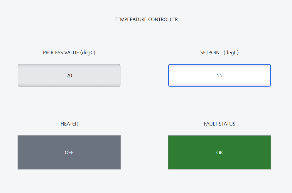
The screen is Configuration/Screens/TempControl.screen.hmi.yml. The key elements are two IOFields (one read-only for actual temperature, one read/write for setpoint), and two status indicators that combine dynamic text with dynamic colour.
The IOFields use different HMI semantics and different visual treatment. Actual temperature is a grey output display; setpoint is a white input/output field with a stronger blue border:
IO_ActualTemp:
  ObjectType: IOField
  IOFieldType: Output
  BackColor: 0xFFE5E7EB
  BorderColor: 0xFF9CA3AF
  BorderWidth: 1
  Dynamics:
    PV_TagDyn:
      ObjectType: TagDynamic
      Tag: TC_ActualTemp
      Property: TempControl.Layers.DefaultLayer.Items.IO_ActualTemp#ProcessValue
      Direction: toProperty
      Indirect: false

IO_Setpoint:
  ObjectType: IOField
  IOFieldType: InputOutput
  BackColor: 0xFFFFFFFF
  BorderColor: 0xFF2563EB
  BorderWidth: 2
  OutputFormat: "%.1f"
  Dynamics:
    SP_TagDyn:
      ObjectType: TagDynamic
      Tag: TC_Setpoint
      Property: TempControl.Layers.DefaultLayer.Items.IO_Setpoint#ProcessValue
      Direction: biDirectional
      Indirect: false
The Property path — TempControl.Layers.DefaultLayer.Items.IO_Setpoint#ProcessValue — is the full address of the property being dynamized. Screen name, layer, item name, then the property name after the #. It is verbose, but it is explicit: there is no ambiguity about which property is wired to which tag.
Direction: toProperty means actual temperature only flows from the PLC tag into the HMI field. Direction: biDirectional means the setpoint field can display the current tag value and accept operator input to write back. This distinction matters in the screenshot too: a measured value should not look like an operator command.
For the heater and fault state labels, I used ResourceListDynamic with a TextListContainers definition. The text list maps Bool values to text entries:
TextListContainers:
  HeaterStateContainer:
    ResourceListType: TextList
    ResourceLists:
      HeaterStateList:
        RangeType: Decimal
        Entries:
          HeaterOff:
            Type: SingleValue
            Value: 0
            Text: Texts.TC_HeaterOff
          HeaterOn:
            Type: SingleValue
            Value: 1
            Text: Texts.TC_HeaterOn
Then in the screen, the label’s dynamic references the list:
Lbl_HeaterState:
  ObjectType: Label
  Text: Texts.TC_HeaterOff
  Dynamics:
    HeaterStateDyn:
      ObjectType: ResourceListDynamic
      Tag: TC_HeatingOn
      Property: TempControl.Layers.DefaultLayer.Items.Lbl_HeaterState#Text
      ResourceList: HeaterStateContainer.HeaterStateList
When TC_HeatingOn is 0, the label shows the text entry for HeaterOff. When it is 1, it shows HeaterOn. No scripting. Pure YAML.
The rectangle colour uses a second dynamic, ScriptDynamic, because BackColor is a colour property rather than text. WinCC UE requires script dynamics to reference a screen-local module named DynamicScripts. In this project the script file is registered explicitly in Main.hmi.yml:
ScriptFiles:
- Configuration/Scripts/DynamicScripts.js
The screen-local module references that file:
ScriptModules:
  DynamicScripts:
    ScriptFile: Configuration/Scripts/DynamicScripts.js
    ScriptLanguage: JavaScript
    Scripts:
      SetHeaterBackColor:
      SetFaultBackColor:
Then the rectangle background is dynamized from the tag:
Rect_Fault:
  ObjectType: Rectangle
  BackColor: 0xFF2E7D32
  Dynamics:
    FaultBackColorDyn:
      ObjectType: ScriptDynamic
      Property: TempControl.Layers.DefaultLayer.Items.Rect_Fault#BackColor
      Script: '@local::DynamicScripts.SetFaultBackColor'
      Triggers:
        FaultBackColorTrigger:
          ObjectType: HmiTagTrigger
          Tag: TC_Fault
The JavaScript itself is small:
export function SetFaultBackColor(item, x, y, modifiers, trigger) {
  const faultActive = Tags("TC_Fault").Read();
  return faultActive ? 0xFFC62828 : 0xFF2E7D32;
}
So the fault indicator is green when TC_Fault is false and red when it is true. The heater indicator uses the same pattern: grey for off, green for on. The text label sits on top of the rectangle, centered, so the rectangle is not decorative; it is the actual state indicator.

Step 4 — Build and Prepare
With everything in place:
# AX side
cd ax-getting-started
apax build
apax test

# HMI side
cd ../ue-intro
apax dm prepare-download
apax dm prepare-download validates the full configuration — YAML schema, tag references, resource list entries, OPC UA connection parameters — and generates the runtime download bundle. If there are schema errors, this is where you see them. Getting this to clean took a few iterations, mostly around learning the exact WinCC ML schema for OPC UA connections and tag cycles.
Once prepare-download is clean, the next step is:
apax dm download --unsecure   # downloads to Unified PC Runtime
apax dm start-runtime --unsecure
Then open https://localhost/WebRH in a browser. The trailing slash matters here: https://localhost/WebRH/ causes WebRH asset paths to resolve incorrectly.
For this article I verified the complete local loop: AX compiled cleanly, the hardware and software downloaded to an S7-1500 instance in PLCSIM Advanced, WinCC Unified PC Runtime started, WebRH rendered in the browser, and the WinCC OPC UA manager established the connection to opc.tcp://192.168.0.1:4840. With the demo values at startup, the runtime shows 0 for the two numeric values, heater OFF, and fault status OK.
What I Learned
The pragma-to-tag path is the cleanest part of this stack. Three lines in configuration.st — two pragmas and a variable declaration — and the variable appears on the OPC UA server. The HMI tag file references the NodeId through WinCC UE’s V:1$DA$... address format. No TIA Portal export cycle and no manual XML manipulation. Just a text file on one side and a text file on the other.
The OPC UA connection schema in WinCC ML has more mandatory fields than the documentation suggests at first. I had to work through a few iterations with apax dm prepare-download and the runtime logs to learn what AuthenticationMode, AuthenticationUserId, AuthenticationPassword, MessageMode, Policy, and the V:1$DA$... address prefix mean in practice. The build-time errors are useful, but the runtime log is what confirmed the final connection.
The TextListContainers schema for ResourceListDynamic is deeper than a simple key-value map. It has a container, a list, and individual entries, each with their own properties. Once you see the pattern it is logical — you can have multiple lists per container, multiple containers per project, and entries with range types, not just single values. But it is not obvious from a first read of the documentation.
One non-obvious trap: the OPC UA browser path and the WinCC UE tag address are not the same thing. My first attempt used a slash-style browse path and the runtime rejected it with an “invalid count of separators ‘$’” error. The installed Siemens tooling revealed the pattern: V:1$DA$<OpcUaNodeId>.
The End-to-End Picture
The smallest loop that connects AX code to a browser-rendered screen:
- Declare globals in
configuration.stwith OPC UA pragmas — two lines - Wire them into the FB call in
MainProgram.st— four assignments - Activate OPC UA in
DomainFunctions.hmi.yml— one boolean - Create the connection and tags in
TempControllerTags.hmi.yml— YAML - Create the screen in
TempControl.screen.hmi.yml— YAML - Load the AX hardware and software to PLCSIM Advanced
apax build(PLC) +apax test(PLC) +apax dm prepare-download/download/start-runtime(HMI)
Everything is a text file. Everything is in git. Every step runs from a terminal. That is the thing I keep coming back to. Not because it is novel for its own sake, but because it makes the engineering visible — readable, diffable, reviewable. The same files that run against PLCSIM Advanced are the files I would expect to review before moving toward a real PLC.
What Is Next
The next few articles will go back to foundations — variables, types, the apax CLI in depth. The HMI series will return for the faceplates article, where this kind of status indicator can become a reusable component instead of being hand-built on a single screen.
If you have shipped AX and WinCC UE on a real project and have a different approach to OPC UA connection configuration, I want to hear it. This stack is young enough that the practical field patterns matter as much as the reference docs.