June 15, 2026 · tia-portalsiemensplc-programmingdata-typesudtindustrial-automationcontrol-systems
The type on a tag is not formatting. It is part of the engineering contract.
The Step After PLC Tags
In the previous article, I wrote about PLC tags and the hardware address space. A tag name makes an address readable, but the address is only half of the declaration.
The other half is the data type.
%I0.0 as a Bool is a pushbutton or a discrete feedback. %IW64 as an Int is a raw word-sized value from the process image. A pressure value scaled into Real is no longer the same thing as the raw input word, even if both values came from the same sensor chain.
That sounds basic. It is basic. But this layer reaches into PLC tags, data blocks, FB interfaces, UDTs, HMI tags, OPC UA clients, source exports, and commissioning habits.
If I choose the wrong type early, the program may still compile. That does not make the model right.
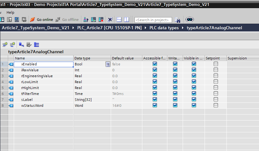
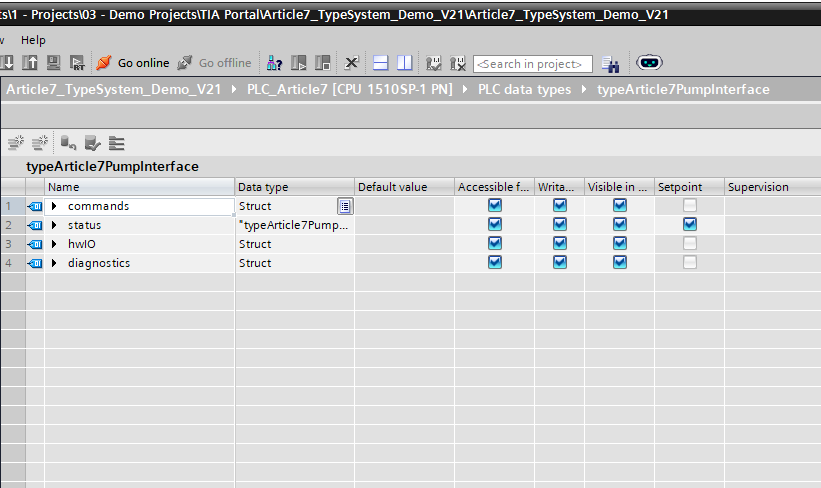
Figure 1. typeArticle7AnalogChannel is a PLC data type in TIA Portal V21. The editor shows how one named type can group related values with explicit elementary types before that shape is reused in DBs, tags, or block interfaces.
A Data Type Says What a Value Is
Siemens groups STEP 7 data types into categories such as elementary data types, complex data types, user-defined data types, parameter types, system data types, and hardware data types. The V21 documentation lists elementary examples such as binary numbers, integers, floating-point numbers, timers, date/time values, and characters; it lists complex examples such as STRING, ARRAY, and STRUCT; and it identifies PLC data types as user-defined data types. Source: Siemens STEP 7 V21 - Overview of the valid data types.
That classification matters because the PLC does not just store “a value.” It stores a value with rules.
Bool is true or false.
Int is a 16-bit signed integer.
DInt gives a larger signed integer range.
Real is a floating-point value, useful for engineering units like pressure, flow, temperature, and speed.
Time is a duration.
Word is a bit string, often useful when I want a compact status or alarm word instead of a number with arithmetic meaning.
String[32] is not the same as an unlimited text field. Siemens documents that a STRING can contain up to 254 characters, and if the maximum length is omitted, the standard length is 254 characters. Source: Siemens STEP 7 V21 - STRING. If I only need a short equipment label, I normally specify the length deliberately.
The point is not to memorize every type. The point is to stop treating the type column as a formality. The type tells the next engineer how the value should be interpreted.
Elementary Types Are Already Design Decisions
Here is a simple pump example:
xStartCommand       Bool
iRawPressureInput   Int
rDischargePressure  Real
tRestartDelay       Time
wAlarmWord          Word
sPumpLabel          String[32]
None of those choices is cosmetic.
The start command is a Bool because there are only two meaningful states. The raw pressure input might be Int because it is still the raw value from an analog input word. The scaled pressure is Real because the control logic should think in engineering units, not raw counts. The restart delay is Time because it is a duration. The alarm word is Word because the bits are status flags, not a signed number. The label is a bounded string because it is operator-facing text with a reasonable maximum length.
I like examples like this because they expose a common mistake: using one type because it is convenient everywhere. A project full of Int values is not automatically simple. It may just be throwing away meaning.
STRUCT Groups Values Without Naming a New Type
Once there are related values, single tags stop being enough.
Siemens describes STRUCT as a data structure with a fixed number of components that can have different data types. Structures can be nested, can contain other STRUCT or ARRAY components, and can be used to group data or transfer parameters as one data unit. Source: Siemens STEP 7 V21 - Basic information on STRUCT.
That is the first jump from “a list of variables” to “a shape.”
Instead of this:
xPumpEnable
xPumpStart
xPumpStop
rPumpPressureSetpoint
xPumpRunning
xPumpFaulted
rPumpPressure
I can group by role:
pump.commands.xEnable
pump.commands.xStart
pump.commands.xStop
pump.commands.rPressureSetpoint
pump.status.xRunning
pump.status.xFaulted
pump.status.rPressure
The second version is not just prettier. It tells me which values are commands and which values are status before I even open the FB logic.
But an anonymous STRUCT has a limit: if I copy the same shape into three different places, I now have three separate declarations to maintain.
That is where a PLC data type, or UDT, earns its place.
A UDT Is a Named Shape
Siemens defines a PLC data type, or UDT, as a complex user-defined data type used to declare a tag. It represents a data structure made from several components of different data types; those components can also be based on another PLC data type, an ARRAY, or a STRUCT. The same page states that a PLC data type can be changed centrally and used repeatedly, with locations of use updated automatically. Source: Siemens STEP 7 V21 - Basics of PLC data types (UDT).
That is the clean mental model: a UDT is a named shape.
In the Article 7 demo project I created a small type called typeArticle7PumpInterface. It contains:
commands      Struct
status        typeArticle7PumpStatus
hwIO          Struct
diagnostics   Struct
Inside that one UDT are elementary types (Bool, Int, Real, Time, String[32], Word), anonymous structures, and nested UDTs.
Figure 2. The pump interface UDT combines anonymous structure members with a nested UDT reference for status.
This is the foundation. A UDT gives a recurring data shape a name, and then that named shape can be used in a DB, a PLC tag, or a block interface.
The deeper question - what belongs in the UDT, how to name it, how to evolve it across project changes - is a design-pattern question. I am deliberately leaving that for a separate article. First I want the vocabulary to be clear.
UDTs Connect Tags, DBs, and FB Interfaces
In Article 5, I wrote about data blocks as first-class objects. In Article 6, I wrote about PLC tags as the hardware vocabulary. UDTs connect both of those articles to function block interfaces.
Siemens documents that PLC data types can be used as data types for tags in logic-block declarations or data blocks. They can also be templates for global data blocks with identical data structures, and they can be used as templates for structured PLC tags on S7-1200 and S7-1500. Source: Siemens STEP 7 V21 - Basics of PLC data types (UDT).
That means the same type can appear in multiple places:
dbArticle7System.pump01 : typeArticle7PumpInterface
classArticle7Pump.interface : typeArticle7PumpInterface
The DB stores the data. The FB receives the same shape through its interface. SCL then reads and writes through structured access:
#interface.commands.xStart
#interface.status.rPressure
#interface.hwIO.q_xRunCommand
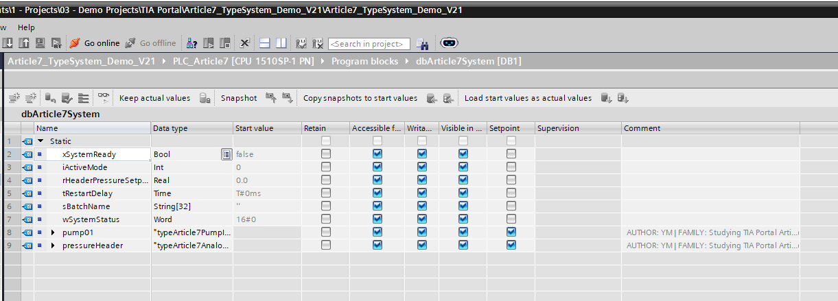
Figure 3. The DB stores instances of the Article 7 UDT shapes as named fields.
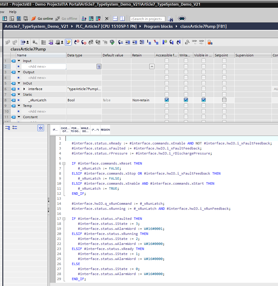
Figure 4. The same UDT shape becomes the block interface contract used by the pump FB in SCL.
This is one reason I like typed interfaces. The block call is smaller, and the contract is clearer. I can pass the pump interface shape instead of a long list of loose parameters.
Siemens makes the same general point in its programming recommendations: PLC data types can reduce the number of parameters supplied to a block call, and a PLC data type can be passed as a complete structure. Source: Siemens STEP 7 V21 - Using PLC data types (UDT).
Structured PLC Tags Are a Specific Case
There is one important distinction from the last article.
If I use a UDT as a structured PLC tag against the hardware address space, Siemens gives specific rules. For structured PLC tags, the documentation says to use separate PLC data types for the Inputs and Outputs operand areas, that structured tags are not permitted in the bit memory address area, and that inputs or outputs from different modules should not be grouped in one PLC data type because module process images are not guaranteed to update synchronously. Source: Siemens STEP 7 V21 - Creating structured PLC tags.
That is different from using a UDT inside a DB or as an FB interface.
So I do not flatten every type-system idea into one rule. A UDT in a global DB, an FB InOut, and a structured input area are related ideas, but the constraints are not identical.
That is why I keep hardware mapping explicit. The type system can help structure I/O, but I still want the hardware boundary to be clear.
The Type System Reaches Outside the PLC
Types also matter when data leaves the PLC.
For OPC UA, Siemens documents that SIMATIC data types do not always correspond one-to-one with OPC UA data types. An S7-1500 CPU provides SIMATIC tags with SIMATIC data types to its OPC UA server as OPC UA tags with OPC UA data types, and clients can read the DataType attribute. Source: Siemens STEP 7 V21 - Mapping SIMATIC data types to OPC UA data types.
The important point is simpler: when a value crosses an HMI, OPC UA, logging, or diagnostic boundary, the data type is part of what the outside system sees.
If I expose a raw Int where the client expects scaled engineering units, the integration may still “work” technically and still be wrong operationally.
My Practical Rule
When I look at a tag, DB field, FB parameter, or UDT member, I ask a few plain questions:
What is this value, not just where is it stored? Who writes it? Who reads it? Is it raw hardware data, scaled engineering data, operator command, block status, internal state, diagnostic bit field, or text? Does it belong alone, or is it part of a shape that should be named?
Those questions lead naturally into the TIA type system. Elementary types give individual values meaning. STRUCT groups related values. ARRAY handles repeated values of the same type. UDTs give a recurring shape a reusable name. DBs store instances of those shapes. FB interfaces consume and produce them.
That is the foundation I wanted to lay before going deeper into UDT design patterns.
I still make mistakes here. Sometimes I choose a type too early and regret it later. Sometimes a loose group of tags should have become a UDT earlier.
But the direction is clear: I want the program’s data model to say what the machine means, not just what memory slot the CPU is using.
If you use a different way to think about TIA types - especially around structured PLC tags, DB interfaces, or UDT boundaries to HMI/OPC UA - I want to hear it. I would rather correct my model than defend a habit that only works in my own projects.
Discussion on LinkedIn: Data types and UDTs in TIA Portal.
Working on something similar?
I am Yuriy Mosiyenko — I design and program industrial control systems, mostly Siemens, as a one-person practice based in Bedford, Nova Scotia, working with customers across Canada. If you have a controls project you cannot staff internally, tell me what you are building.
