May 18, 2026 · tia-portalsiemensplc-programmingorganization-blocksindustrial-automationcontrol-systems
The runtime decides when your code runs. OBs are the interface between that decision and you.
The Thing TIA Decides Before You Write a Single Line
Every PLC platform makes execution decisions on your behalf. The question is how visible those decisions are.
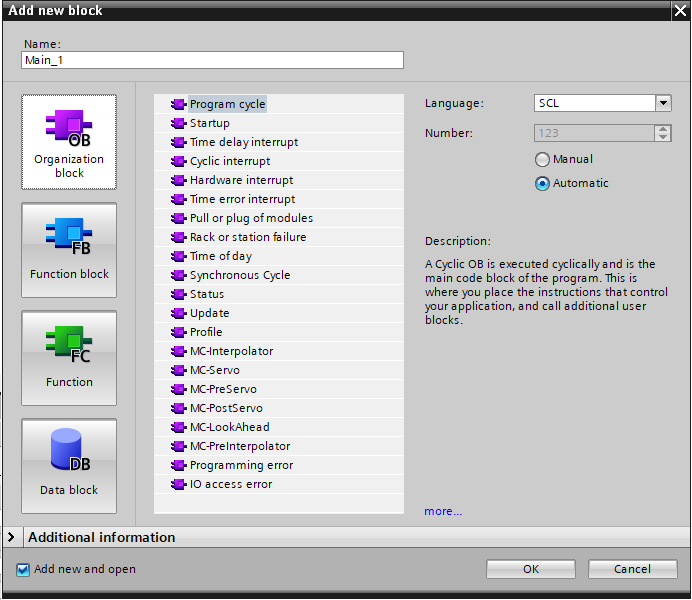
In TIA Portal, that visibility lives in the Organization Block. OBs are the entry points into your program — the only blocks the runtime calls directly. Everything else — function blocks, functions, data blocks — exists inside OBs or is invoked from inside them. You never call an OB from your own code. The runtime calls them. That distinction is the whole execution model in one sentence.
It sounds simple. In practice, understanding which OBs exist, what triggers each one, and what the runtime does when two interrupt simultaneously is the difference between a program that behaves predictably and one that produces surprises at 2 AM on commissioning night.

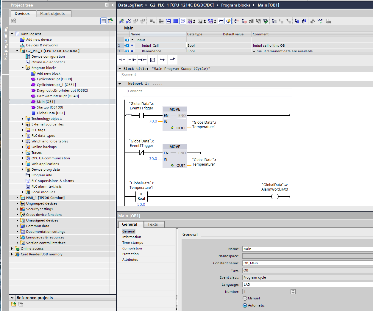
OB1 — The Scan Cycle Made Visible
OB1 is the main cyclic block. As long as the CPU is in RUN mode, the runtime calls OB1 continuously — it executes, finishes, and the runtime calls it again immediately. That loop is the scan cycle.
Before going further: this behavior is a Siemens design choice, not a universal PLC behavior. It is worth understanding what that means, because the industry does not agree on one model here.
On an S7-1500, the cycle time is explicitly variable. The Siemens documentation states it directly: “The cycle time is therefore not the same for every cycle.” Code volume, interrupt OBs preempting OB1 mid-scan, and communication processing the runtime handles in the background all affect how long any given scan takes.
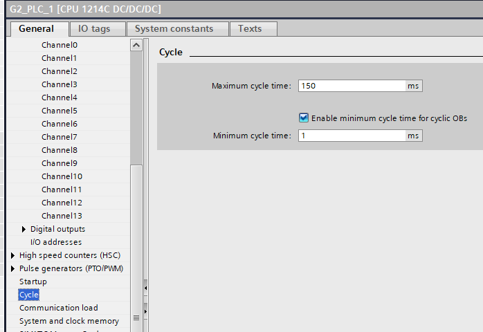
There is a configurable minimum cycle time (default 1 ms) — if OB1 finishes faster, the CPU waits before starting the next scan, processing queued events during that gap. But there is no fixed upper bound on how long a scan takes, only a watchdog maximum (default 150 ms) that triggers a fault if exceeded.
Other platforms handle this differently.
On Beckhoff TwinCAT, the default model goes in the opposite direction: when you create a new PLC project, TwinCAT generates a task with a 10 ms fixed cycle time. The code runs, finishes, and the CPU waits until the next scheduled tick. If the code takes less than 10 ms, the remainder of the interval is idle time — other tasks can use it. The interval is the contract, not the code load. This is deterministic at the scheduler level: a TwinCAT PLC task runs every 10 ms regardless of what the code does.
Codesys — the runtime used by WAGO, Eaton, ABB AC500, Bosch Rexroth, and others — offers both models explicitly. The standard project creates a cyclic task with a configured fixed interval. But Codesys also provides a freewheeling task — one that executes “as often as possible” without a fixed cycle time, behavior that is closer to what Siemens does with OB1. The choice between them is the engineer’s, and Codesys documents both as valid options.
Rockwell’s ControlLogix lands closest to Siemens: the default task in Studio 5000 is a continuous task, which runs as fast as the processor can execute logic with no idle time between scans. Scan time is variable. Rockwell also offers periodic tasks — fixed-interval execution — for time-critical work, and engineers commonly use them for PID loops and motion calculations where a known execution interval matters.
SIMATIC AX — Siemens’ newer code-based PLC platform — makes cycle scheduling an explicit engineering decision rather than a fixed convention. When you write TASK Main(Priority := 1) with no Interval, AX behaves like TIA Portal OB1: free-running, variable cycle time, re-queued immediately after each scan completes. Add Interval := T#100ms and the same TASK construct becomes a deterministic cyclic interrupt — the runtime fires a TimeError if the program overruns the period. The choice lives in a single line of code. The engineer declares the contract; the S7-1500 firmware enforces it.
For engineers familiar with TIA Portal’s OB structure, it is worth noting that AX’s TASK configuration lives in the project structure’s configuration file, not in a CPU properties dialog — a meaningful shift in where that decision is made.
The pattern across these platforms is that fixed-interval execution and variable execution are both legitimate models, implemented differently depending on the platform’s design philosophy. Siemens TIA Portal and Rockwell default to variable-duration main scans. Beckhoff defaults to fixed-interval. Codesys offers both explicitly. SIMATIC AX makes the choice per-task in a single line of code. IEC 61131-3 defines task types that include both cyclic (fixed interval) and freewheeling — the standard does not mandate which must be the default.
What this means when reading TIA Portal code: OB1’s duration is not a fixed window you can rely on for timing. It varies with every scan. If you come from a Beckhoff or Codesys background where the main task runs on a fixed tick, this difference matters — code that worked fine in a 10 ms fixed task may behave differently when the scan time can stretch. For logic that genuinely needs a deterministic interval on a Siemens CPU, the answer is the cyclic interrupt OBs discussed in the next section.
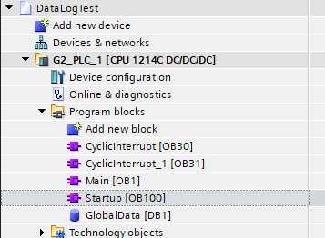
OB100 — The One-Time Block Nobody Skips Twice
OB100 is the startup block. It runs once when the CPU transitions from STOP to RUN. That is its entire job. After it finishes, the runtime begins calling OB1 cyclically.
The practical importance of OB100 is larger than “run some initialization code.” A PLC program that starts in a known, safe state is fundamentally more reliable than one that inherits whatever values were in the data blocks from the previous power cycle. On S7-1500, retentive memory preserves specific variables across power cycles by design — which is useful for accumulating runtime hours and alarm counters. But control logic state, PID integrators, ramp generators, and mode flags typically need to start from a defined condition, not from whatever the last power cycle left behind.
The failure mode when you skip this is often subtle. The code runs, the outputs sequence through what looks like normal behavior, and then something unexpected happens in the first operating cycle. I have run into this kind of bug more than once — the symptom appears random because the starting state is unpredictable. OB100 is where you prevent it.
For engineers from platforms where startup initialization is handled differently — through first-scan logic in the cyclic program, or through language-level variable initialization — the TIA pattern is: put it in OB100, not in OB1. There is a dedicated OB for this exactly because the runtime distinguishes between “first scan” and “every scan.”
One thing OB100 does not handle on its own: recovery from loss-of-communications mid-operation, or from certain STOP conditions that are not a full power cycle. Those cases warrant their own thinking, which goes deeper than OB100’s scope. The initialization article later in this series will go into that territory.
OB30 to OB38 — When Fixed Timing Matters More Than the Scan
Cyclic interrupt OBs run on a fixed time interval, independent of OB1’s scan cycle. The runtime fires them at their configured interval regardless of where OB1 is in its current scan. OB1 is preempted, the interrupt OB runs to completion, and OB1 resumes.
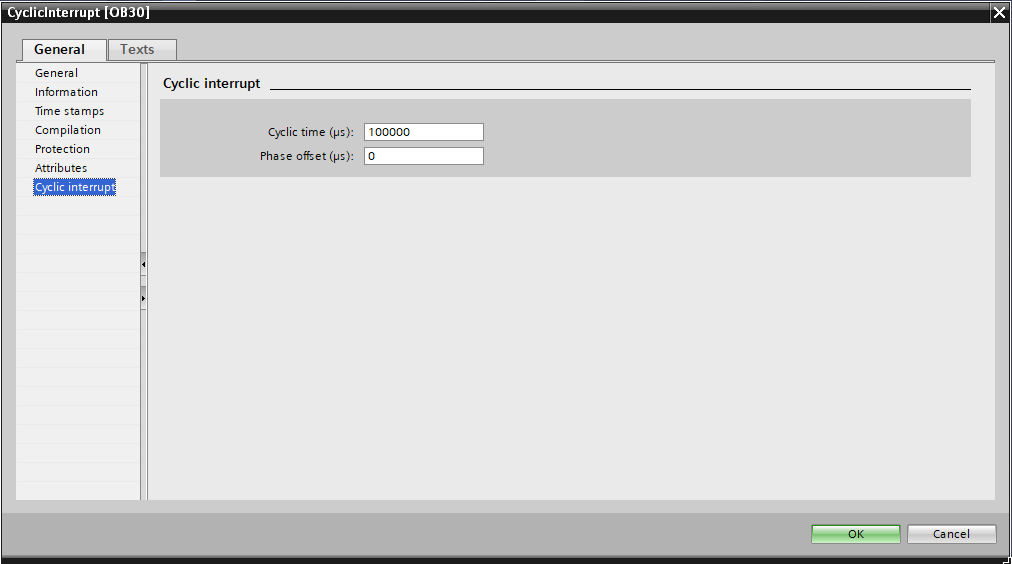
The default cyclic interrupt OBs in TIA are numbered OB30 through OB38. Each can be configured with a specific time interval and a phase offset. The phase offset is worth understanding: if you have two cyclic interrupt OBs both set to fire at 10 ms, they would normally pile up at the same moment. A phase offset staggers their start times, preventing the spike in processor load that simultaneous firing would cause. The Siemens documentation for S7-1200 G2 (and the same principle applies on S7-1500) describes this explicitly and makes it configurable in OB properties.
When do you reach for a cyclic interrupt OB instead of putting everything in OB1? When you have logic that genuinely needs to execute at a known, bounded interval independent of how long the rest of the program takes.
The classic case where cyclic interrupt OBs earn their place is a PID control loop — and PID loops are everywhere in industrial control: temperature, level, flow, pressure, any domain where you are regulating a process variable. The reason is in the math: a PID’s integral term accumulates error over time, and the derivative term estimates rate of change. Both depend on a known, fixed time step (dt) between successive calls. If dt varies with the scan cycle — stretching when communication overhead or an unusual code path hits — the integrator drifts and the derivative becomes noisy. The control output degrades in ways that can be difficult to diagnose. Putting the PID calculation in a cyclic interrupt OB with a fixed interval makes dt deterministic, and the algorithm works as designed.
The risk with cyclic interrupt OBs is overrun — when the logic inside the OB takes longer to execute than the configured interval. The documentation describes this: if a cyclic interrupt event fires before the previous call has finished, the new event is counted as discarded. On S7-1500, TIA reports these discarded events as a diagnostic. An OB with a high discard count is a signal that the interval is too short for the code inside it, or that the code needs to be optimized.
A practical rule I follow: if the logic in a cyclic interrupt OB can tolerate the occasional missed cycle without consequences, the overrun is manageable. If missing a cycle causes a safety or quality problem, you need a shorter, more efficient OB — or a different architecture. This is an engineering judgment, not a formula.
Hardware Interrupt OBs — Fast Response to Discrete Events
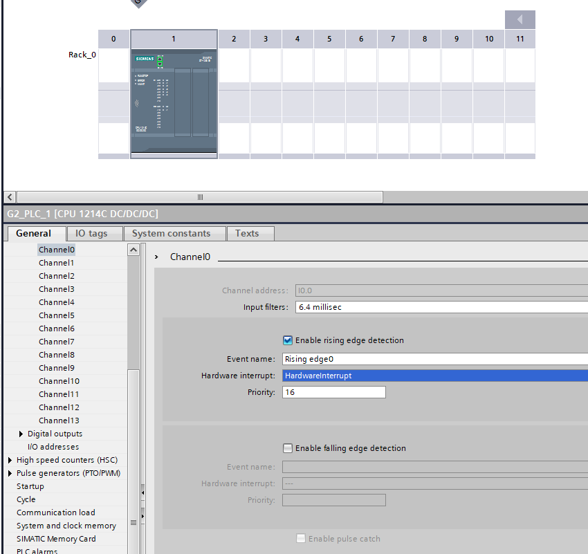
Hardware interrupt OBs fire when a hardware signal changes state — specifically, when a digital input configured for hardware interrupt triggers an event. The runtime drops whatever it is doing in OB1 and executes the hardware interrupt OB immediately.
The use case I remember most clearly for this is a CTD winch project from a few years ago. A CTD — Conductivity, Temperature, Depth — is a scientific instrument used in oceanographic work. The deployment system hauls the CTD back up through the water column and into a compression head on deck. The moment the compression head is nearly fully compressed, the winch has to stop. Immediately. Not “at the next scan.” Now.
The failure mode is specific and expensive. If the springs in the compression head compress completely before the winch stops, the wire detaches from the CTD at its termination. The CTD drops into the ocean. A loss of several hundred thousand dollars, instantly.
A scan cycle is too slow to guarantee this response. The answer was to wire the compression sensors directly to digital inputs configured for hardware interrupt, and put the winch stop logic in the hardware interrupt OB. When the sensors trigger, the runtime drops OB1 immediately and executes the interrupt OB — the winch output goes off before the scan cycle would have even seen the event.
That is the real use case for hardware interrupt OBs: not a conceptual example, but a situation where the consequence of missing the event by even one scan cycle is unacceptable.
What I have found in practice is that most applications do not need hardware interrupt OBs. A servo controller handling position feedback is better managed through the motion control OBs (MC-Servo and MC-Interpolator) on S7-1500 — which have their own deterministic calling pattern. A standard discrete-event response — a button press triggering a sequence, a limit switch stopping a motion — typically works fine through OB1 because the response time requirement is measured in tens of milliseconds, well within a normal scan cycle.
When a hardware interrupt OB is genuinely the right tool, the logic inside it should be as short as possible. A hardware interrupt OB that runs for 50 ms is counterproductive — it preempts OB1 for the entire duration and introduces latency elsewhere. Set a flag, capture a timestamp, update a register. Do the heavy lifting in OB1.
Diagnostic OBs — The Program Watching the Hardware
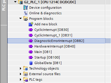
TIA Portal calls diagnostic OBs when hardware events occur that the control logic may need to respond to. OB82 fires when a diagnostics-capable module reports a change in its diagnostic status — a wire break on an analog input, an out-of-range sensor, a module fault. OB86 fires on rack or station failure — a PROFINET device going offline, a distributed I/O rack losing power.
Neither of these requires code to be present. If OB82 is not in the project, TIA Portal handles the diagnostic event at the system level — the CPU logs it and continues. If OB82 is present, the runtime calls it with start information identifying which module raised the event, and the engineer’s code inside OB82 can respond: set an alarm flag, log the event to a data block, put the system into a safe state.
A pattern I would recommend: OB82 and OB86 are present but minimal. They set a flag in a global data block. The cyclic logic in OB1 reads that flag and handles it — transitioning state machines to fault states, activating alarms, taking whatever action the application requires. This keeps the interrupt handler short and puts the response logic where it can be tested and monitored.
What TIA Decides and What You Decide
The deeper point about OBs is the boundary they define.
TIA Portal’s runtime decides which OB to call, when to call it, and with what start information. You cannot change the calling order for the cyclic interrupt OBs relative to their configured intervals. You cannot call OB100 from within OB1. The runtime owns the execution schedule.
What you decide is everything inside the OBs — the logic, the sequencing, the data flow, how the OBs coordinate with each other through global data blocks. You also decide which OBs exist in the project at all. An OB that is not present does not consume resources and does not influence execution.
For engineers who come from platforms where execution control is more explicit — where a main routine calls subroutines in order, where you define the scan explicitly — this inversion can take some adjustment. The runtime-drives-you model means the execution contract is defined by the OB type and its trigger condition. Once you understand those triggers, the model is actually quite predictable.
What sometimes catches engineers is the interaction between multiple OBs: a cyclic interrupt preempting OB1 mid-scan means OB1’s logic does not complete atomically. If two OBs share data without handling that preemption correctly, you can get inconsistent reads.
The framing I find useful: OBs are the contract between the hardware/runtime layer and the engineer-written code. The runtime holds up its end by calling the right OB at the right time. The engineer’s job is to write code that works correctly within each OB’s timing and priority constraints.
A Few Things I Would Do Differently If Starting Now
If I were setting up a new S7-1500 project today, I would put a minimal startup sequence in OB100 on day one, even if I did not yet know what initialization was needed. A placeholder OB100 with a comment block is easier to build on than scrambling to add startup logic later when a commissioning bug surfaces.
I would also be conservative about cyclic interrupt OBs. They are useful for the specific problem they solve — deterministic timing when OB1 scan variance matters. But every cyclic interrupt OB adds scheduling complexity, and a project with four of them at different intervals starts to require real thought about the interaction between them. I would rather start with OB1 and move logic to a cyclic interrupt OB when a concrete timing requirement justifies it.
If you organize this differently — a pattern for OB100 initialization that has worked better, a systematic approach to phasing multiple cyclic interrupts, or a case where hardware interrupt OBs turned out to be the right call for a problem I described as rare — I want to hear it. I would rather hear a better way to think about this than be right about how I have framed it.