June 1, 2026 · tia-portalsiemensplc-programmingplc-tagsio-mappingindustrial-automationcontrol-systems
A PLC tag can make an address readable. It does not automatically make the program well structured.
The Step After Data Blocks
In the previous article, I wrote about data blocks as first-class objects in TIA Portal. That article was about where program data lives and why it matters that DBs are visible engineering objects.
Now I want to move one layer closer to the hardware.
TIA Portal projects also have PLC tags. Most engineers meet them early: a table of names, data types, comments, and addresses. StartButton points to %I0.0. MotorRun points to %Q0.0. An analog signal might point to %IW64 or %QW64.
This seems simple, and in one sense it is. But I have seen projects where the tag table slowly becomes the architecture of the PLC program. Every internal idea becomes a global tag. Every sequence step becomes an M bit. Every function block reads directly from hardware addresses because “it works.”
That is where the trouble starts.
A PLC tag table is extremely important, but I do not treat it as the place where the system architecture should live. I treat it as a vocabulary layer between the PLC program and the hardware address space.

What PLC Tags Actually Do
Siemens describes the basic mechanism clearly: to address a PLC tag, you can use either the absolute address or the symbolic name. The same official STEP 7 page shows examples such as %Q1.0, %I16.4, and %IW4, and it also shows structured symbolic access such as "Structured_Tag".Element for a tag based on a PLC data type. Source: Siemens STEP 7 V20 - Addressing PLC tags.
That is the key idea: a PLC tag gives a name to something the PLC can address.
The address side belongs to the CPU’s memory and hardware model. Siemens documents that PLC tag addresses are made from an operand area plus an address inside that area. The common operand areas include I for input, Q for output, and M for bit memory. Siemens also states that PLC tag addresses must be unique throughout the CPU, and duplicate assignments are highlighted with an error. Source: Siemens STEP 7 V21 - Permissible addresses and data types of PLC tags.
So a tag table is partly documentation, partly declaration, and partly an address map.
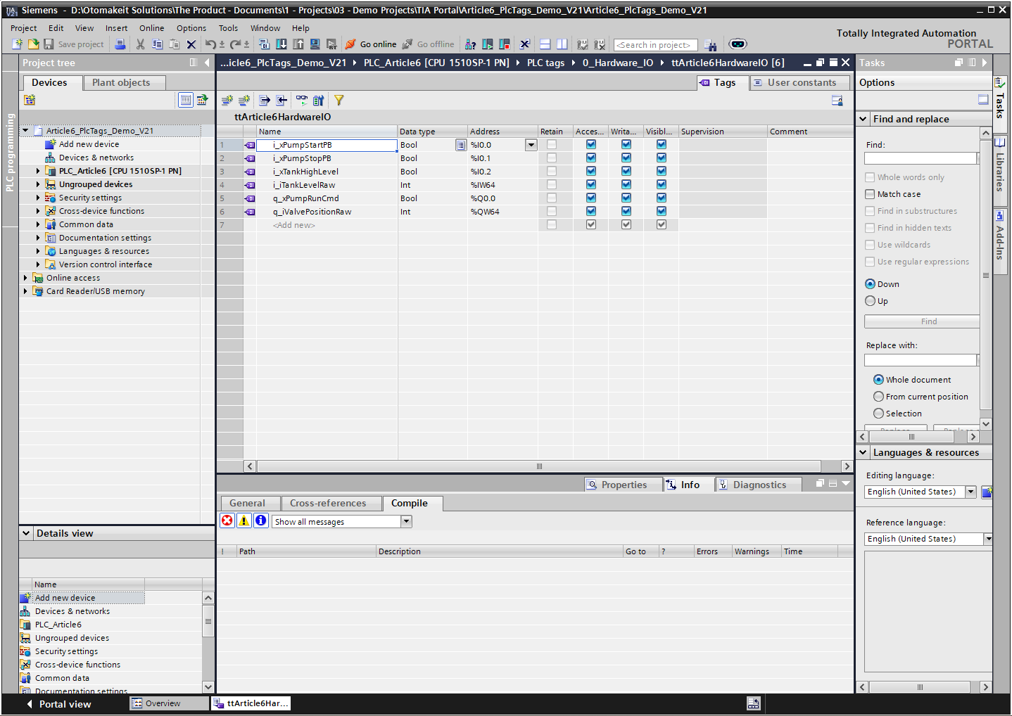
When I name %I0.0 as "i_xPumpStartPB", I am not changing the electrical reality. The input still comes from a physical terminal or module channel. The tag gives that signal a useful name in the PLC project.
That is valuable. Nobody wants to read raw addresses everywhere.
But it is also easy to overestimate what the name does.
If I give %M10.0 a beautiful symbolic name, it is still M memory. If I give %Q0.0 the name "q_xPumpRunCmd", it is still a physical output address. Symbolic names improve readability. They do not automatically create ownership, modularity, testability, or reuse.
Those things come from architecture.
I, Q, M, and DB Are Not the Same Kind of Space
I think engineers sometimes mix all PLC-accessible data into one mental bucket: “tags.”
That hides an important difference.
I and Q are tied to the hardware interface. Inputs are the PLC’s view of the outside world. Outputs are the PLC’s commands back to the outside world. Their addresses have electrical meaning.
M is memory inside the CPU. It can be useful, especially for simple legacy patterns, quick tests, or compatibility with older habits. But it is global memory with absolute addressing. If a modern project grows around M bits, the program starts depending on a hand-managed memory map.
DB data is different again. A DB can hold structured program data, settings, HMI commands, status, diagnostics, recipes, or instance state. It can be typed, grouped, monitored, and owned by a block or interface.
The difference matters because each area answers a different engineering question.
An I tag answers: “Where does this field signal enter the PLC?”
A Q tag answers: “Where does this PLC command leave toward hardware?”
An M tag answers: “Where is this bit or word in CPU memory?”
A DB tag answers: “Where does this program data live in the software model?”
That is why I am careful with the phrase “PLC tags.” It is a broad feature in TIA Portal, but not every tag has the same architectural meaning.
Hardware Names Are Not Program Architecture
I like descriptive I/O tags. I want the raw hardware layer to be readable.
For example:
i_xPumpStartPB      %I0.0
i_xPumpStopPB       %I0.1
i_xTankHighLevel    %I0.2
i_iTankLevelRaw     %IW64
q_xPumpRunCmd       %Q0.0
q_iValvePositionRaw %QW64
This is already much better than raw addresses scattered through the program.
But I do not want a pump control FB reading "i_xPumpStartPB" directly and writing "q_xPumpRunCmd" directly. That couples the FB to the exact wiring of this project. If I copy the FB to another machine, I either carry the same I/O names with it or edit the block.
That is not reusable control logic. That is hardware-specific logic with nice labels.
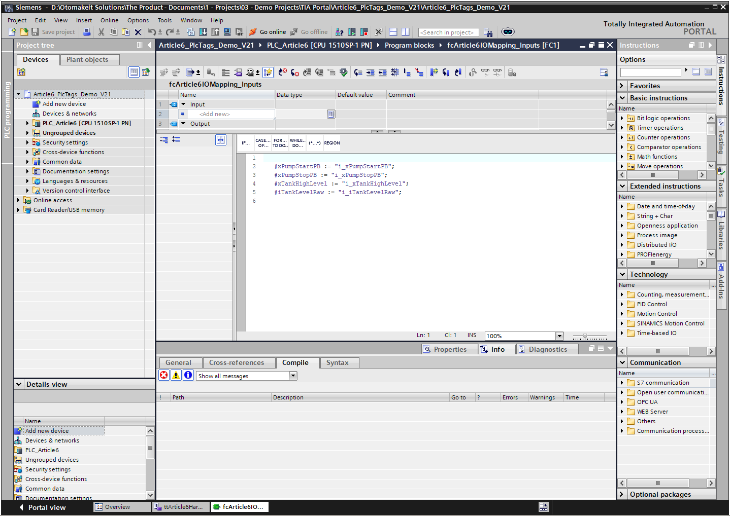
The pattern I prefer is to keep hardware access in a mapping layer. OB1 calls input mapping first, then the system or equipment FBs, then output mapping at the end.
OB1 cycle
1. fcArticle6IOMapping_Inputs
2. classArticle6Pump or other equipment FBs
3. fcArticle6IOMapping_Outputs
In this compact demo, the input mapping reads the PLC tags and writes symbolic output parameters:
#xPumpStartPB := "i_xPumpStartPB";
#xPumpStopPB := "i_xPumpStopPB";
#xTankHighLevel := "i_xTankHighLevel";
#iTankLevelRaw := "i_iTankLevelRaw";
In a larger project, those same mapped values normally land in a typed system DB or equipment interface structure.
The pump FB then works with symbolic parameters or a project interface structure, not with %I0.0 or %Q0.0.
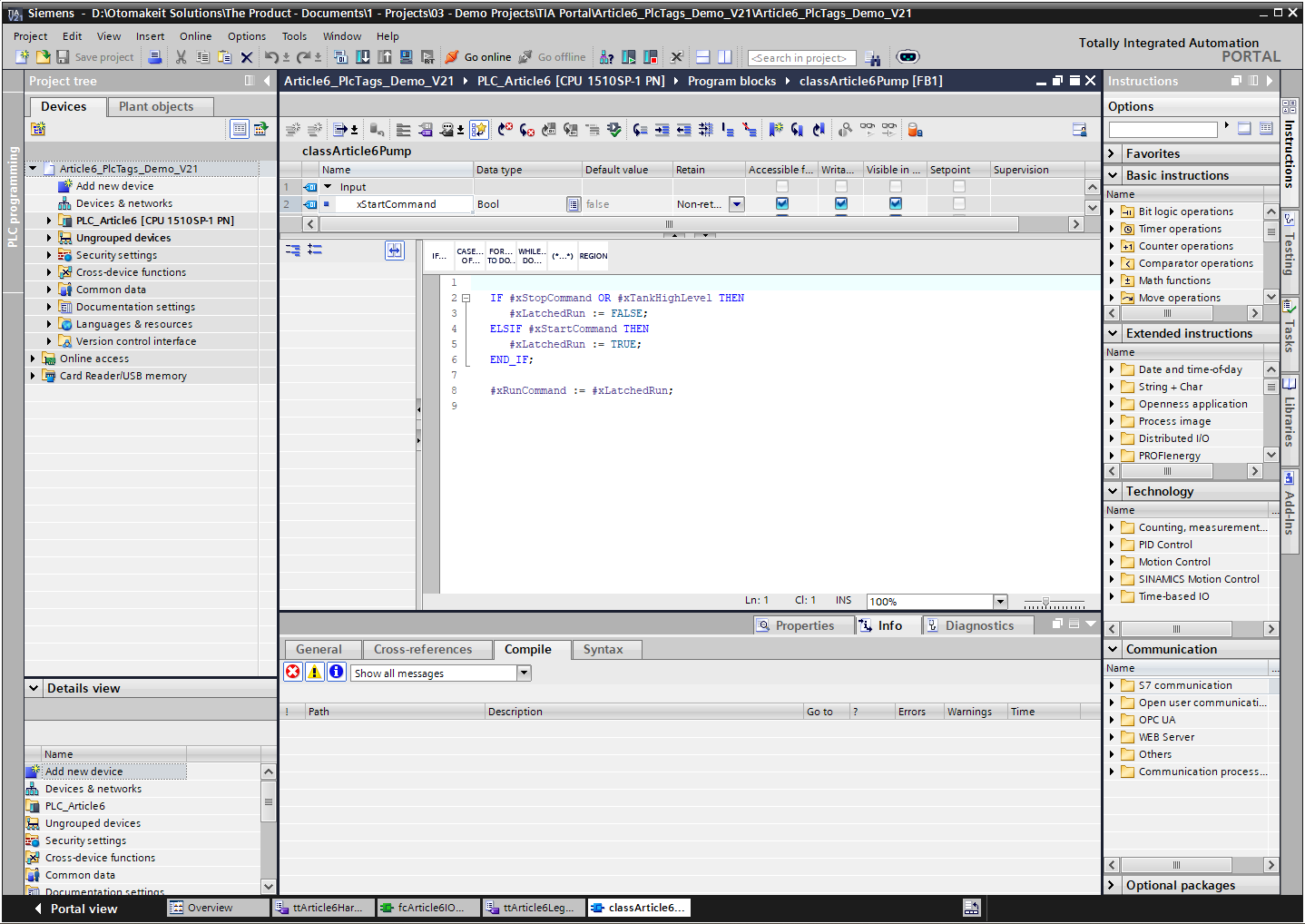
This gives me a clean separation.
If the electrician moves the start pushbutton from %I0.0 to %I2.3, I update the PLC tag address; if the signal name or interface changes, I update the mapping. The pump FB does not care. If I simulate the pump FB, I can drive the interface data without real hardware. If I reuse the pump FB in another project, I bring the logic and interface, not the old I/O map.
That is the difference between using tags for readability and using architecture for maintainability.
Why I Avoid M Bits as the Backbone
I want to be precise here. I am not saying “M memory can never be used.”
I am saying I do not want M bits to become the architecture of a modern TIA Portal program.
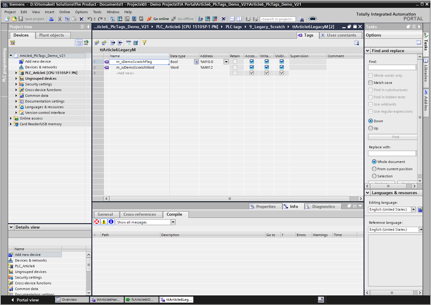
The problem is not only that M10.0 looks ugly. TIA lets me give it a symbolic name. The problem is that M memory is global and absolute. It has no natural equipment ownership, no typed structure, and no instance boundary.
This is where old habits become expensive. A project starts with a few convenient flags:
m_xPumpAutoRequest     %M10.0
m_xPumpFaultLatch      %M10.1
m_xTankFillingStep     %M10.2
Then another section uses more M bits. Then a word is added. Then someone has to know whether a bit, byte, word, or double word overlaps something else. Siemens’ own tag rules are built around unique CPU addresses and duplicate-address warnings, but a good architecture should not rely on engineers manually remembering a global scratch map.
DBs and FB instance data give me better places for most internal state.
If the state belongs to one pump FB, I put it in that FB’s Static section. If it is part of the HMI command/status interface, I put it in a structured DB. If it is a diagnostic word, I put it in a diagnostics structure with a clear owner.
The question I ask is simple: who owns this value?
If the answer is “everybody, somewhere, maybe,” the program is already becoming harder to maintain.
Tag Tables Still Deserve Structure
Even though I do not treat PLC tag tables as the architecture, I still organize them carefully.
TIA Portal lets projects group PLC tags in tag tables and folders. Siemens’ Openness documentation also says that tags are often grouped in tag tables and hierarchical folder structures during export/import. Source: Siemens TIA Portal Openness V20 - Export/Import of PLC tags.
That matches how I like to keep real projects readable.
For a demo project, I might separate tag tables like this:
PLC tags
  0_Hardware_IO
    ttArticle6DigitalInputs
    ttArticle6DigitalOutputs
    ttArticle6AnalogInputs
    ttArticle6AnalogOutputs
  9_Legacy_Scratch
    ttArticle6LegacyM
The exact names are less important than the intent. Inputs and outputs should be easy to find. M memory, if used, should be visible and contained. I do not want a single giant tag table where a new engineer has to scroll through everything.
This is also why I like consistent prefixes. In my own projects, I prefer the name to tell me direction and type:
i_x...  input BOOL
q_x...  output BOOL
i_i...Raw / q_i...Raw  raw Int analog values tied to IW/QW addresses
i_r... / q_r...        scaled Real analog values used inside the program
The prefix is not magic. It is just a useful convention. The real discipline is that the tag table should make the hardware layer understandable without pretending to be the whole software design.
HMI Tags Are Another Reason to Prefer Symbolic Names
Symbolic naming also matters outside the PLC.
For WinCC Unified external tags, Siemens documents both symbolic and absolute addressing, and says to use symbolic addressing if possible because it enables high-performance data access, is less prone to errors, and lets the system update locations of use when assignments change. Source: Siemens WinCC Unified V20 - Creating external tags.
That is a good reason to avoid building HMI communication around raw addresses.
But I still prefer to expose a deliberate interface to the HMI. The HMI should not need every internal latch, timer bit, and temporary state from the PLC. It should see commands, statuses, settings, alarms, and diagnostics that were designed as an interface.
So again, symbolic addressing helps. But architecture decides what should be exposed.
My Practical Rule
Here is where I land.
Use PLC tags to name the hardware address space clearly.
Use symbolic names instead of raw addresses in normal program work.
Organize tag tables so inputs, outputs, analog signals, and any legacy M memory are easy to inspect.
Do not let PLC tags become the structure of the whole program.
Keep direct I/O access in mapping functions. Let equipment FBs work with typed interfaces and DB structures. Put internal state inside FB instances or clearly owned DB sections. Be very cautious when M memory starts spreading across a project, because it usually means ownership is missing.
TIA Portal gives us both absolute addresses and symbolic names. That is useful. The address tells the CPU where something is. The symbol tells the engineer what it means.
But a clean program needs one more layer: responsibility.
Who owns this value? Who writes it? Who reads it? Is it hardware, interface data, internal state, or diagnostics?
When those answers are clear, PLC tags become what they should be: a readable hardware vocabulary.
When those answers are not clear, the tag table becomes a global memory map with nicer names.
I have seen enough of both to know which one I want to keep building.