May 7, 2026 · tia-portalsiemensplc-programmingindustrial-automationcontrol-systems
A structured look at OBs, FBs, FCs, DBs, instances, tags, and types — before we go deeper on any of them.
Why This Article Is Worth Your Time
I planned to go straight into UDT design patterns. While writing that piece I realized it kept assuming vocabulary I had never actually laid out, so this foundations article comes first.
If you have been in TIA Portal for any length of time, you already know these building blocks exist. You have created function blocks, dropped data blocks into a project, called FCs from inside an OB.
But knowing the pieces individually is different from understanding how they connect and why TIA made the design choices it did. That second part matters when you are trying to understand why a program behaves a certain way, or when you are looking at someone else’s project structure and trying to figure out what logic lives where.
It also matters for engineers who have worked on other platforms — Allen-Bradley or Codesys. The vocabulary overlaps, but the choices are different. Some things TIA does are not universal. Knowing what TIA chose deliberately helps you use it intentionally rather than by habit.
The Building Blocks
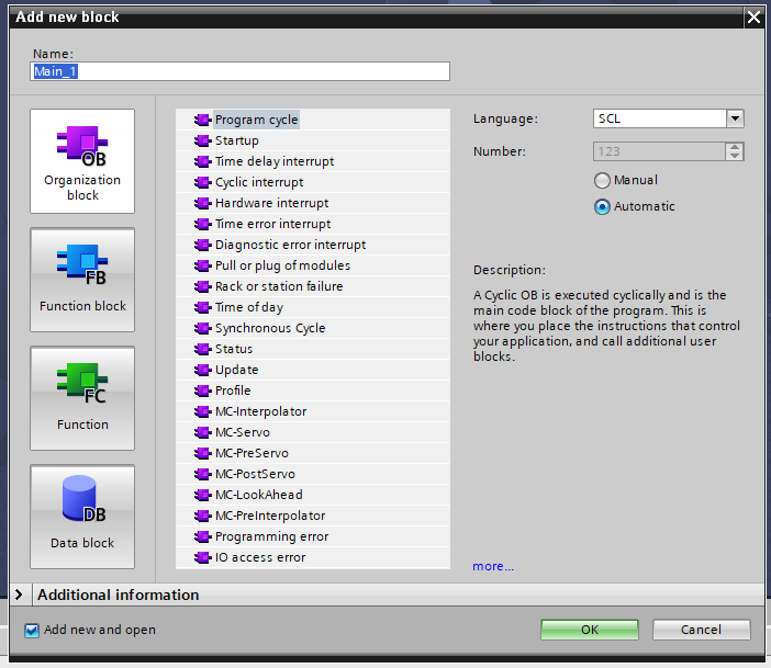
Organization Blocks (OBs) are where execution begins. When the PLC runs, TIA decides which OB to call based on what triggered it — a cyclic timer, a startup event, a hardware interrupt, a diagnostic event. OB1 is the main cyclic block that runs continuously. OB100 runs once at startup. OB30 through OB38 are cyclic interrupts that run at fixed time intervals independently of OB1.
You do not call OBs from your code. The runtime calls them. Everything else — the function blocks, the functions, the logic — lives inside OBs or is called from inside them.
Function Blocks (FBs) are reusable code units that retain state between calls. Each instance of an FB has its own memory — its own timers, its own counters, its own internal variables. If you have three identical conveyor drives and you want each one to track its own fault state and runtime hours, you write one FB and create three instances. The code is shared; the data is not.
Functions (FCs) are stateless. An FC executes, returns a value or modifies outputs, and leaves no trace behind when it is done. Call it a hundred times from a hundred different places and it has no memory of any previous call. FCs are the right tool for calculations, conversions, and logic that does not need to remember anything.
Data Blocks (DBs) are where TIA stores data as first-class objects in the project. A global DB holds data that any block in the program can read or write. An instance DB belongs to a specific FB and holds that FB’s internal state.
This is worth pausing on, because it is a deliberate design choice, not the only valid model. In SIMATIC AX — which I wrote about earlier in an AX series article — there are no separate DB files. Global data lives in a VAR_GLOBAL section inside the CONFIGURATION declaration. Instance data is created automatically when you declare a variable of an FB type. AX chose to fold data into language declarations. TIA chose to make DBs visible, nameable objects you can monitor, initialize, and retain independently. Neither is wrong. They are different tradeoffs, and TIA’s choice means data is always explicit and browseable in the project tree, which has real advantages for commissioning and diagnostics.
Instances are what happens when you put an FB into service. The FB itself is a definition — a type. When you drag it into OB1 and give it a name, or declare a variable of that FB type in a global DB, you create an instance. That instance gets its own DB, its own copy of all internal variables, and its own memory. The same FB code, running with different data, producing independent behavior for each instance. A winch controller FB with four instances is four independent controllers running the same algorithm on different load cell readings and different position setpoints.
PLC Tags are the symbolic names you give to hardware addresses. Instead of writing %I0.0 in your code, you define a tag called ConveyorStartButton mapped to %I0.0, and you use the name. Tags live in the tag table. The address spaces in TIA are I (inputs from the field), Q (outputs to the field), and M (memory bits and bytes internal to the PLC). Tags give the hardware a vocabulary the rest of the program can use without caring about physical addresses.
Data Types and UDTs are the system for giving structure to data. TIA’s built-in types — BOOL, INT, REAL, WORD, TIME, and so on — are the primitives. User-Defined Types (UDTs) are the engineer’s tool for grouping those primitives into something meaningful. A tank has a level setpoint, a current level reading, a high-level alarm, and an auto/manual mode. You define a UDT for that group, and then you can declare a variable of that type wherever you need it. Instead of fourteen separate variables scattered across a DB, you have one structured variable that travels as a unit. The depth of how to design UDTs well — the decisions that survive real project change requests — is its own article. For now, the concept is all you need.
How They Fit Together
The shape of a TIA Portal program is the same regardless of what it controls.
The OBs are at the top. When a scan cycle runs, OB1 fires. OB1 calls function blocks and functions. Those blocks read from and write to data blocks. They read from and write to tags — which are ultimately the hardware inputs and outputs. The scan cycle completes, and TIA does it again.
In practice the structure I use on a recent industrial project looked like this: an IO mapping FC at the top of OB1 copies hardware addresses into a structured global DB, making every hardware signal available by name. Then a set of function blocks run in sequence — device-layer FBs for individual sensors and actuators, function-layer FBs for control logic, a system-layer block that coordinates the whole. Each FB has its own instance DB. All the data those blocks need to share lives in the global DB.
Inside the Program blocks folder in that project, the structure is 0 Interfaces, 1 Systems, 2 Functions, 3 Devices, 4 SIMULATION, 9 Data. The numbering is intentional — it reflects execution order and dependency level. Devices at the bottom, systems at the top, data separate. The organization is not arbitrary; it is the shape that makes the program readable to a different engineer when they pick it up later.
That structure is where the next few articles will go deeper — first into the pieces themselves, then into how to organize them in ways that hold up under real conditions.
What’s Next
The next article goes deeper on one of these pieces. I will commit to which one when I know which thread has the most useful ground to cover first — that has been my approach with this series and it is working better than a fixed syllabus would.
If you are coming from Allen-Bradley, Codesys, or another platform and something about how TIA structures a program struck you as unexpected — I want to hear it. I would rather hear a better way to think about this than be right about how I have framed it.